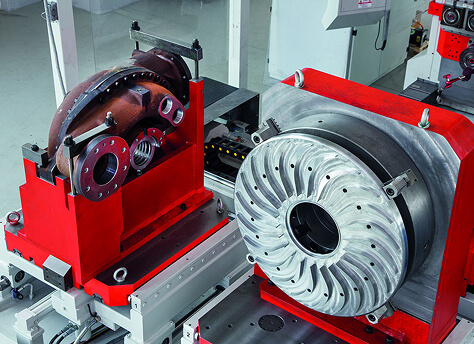
In high-stakes manufacturing environments such as aerospace, oil and gas, maritime defense, and heavy industrial machinery production, manufacturing engineers face a persistent, margin-eroding problem: the inefficiencies of multi-setup machining for large, geometrically complex workpieces. Traditional approaches dictate routing a single casting or heavy forging across multiple machine tools—typically a Vertical Turning Lathe (VTL) for concentric turning, followed by a Horizontal Machining Center (HMC) for prismatic milling, drilling, and tapping, and finally a line-boring machine for precision deep bores.
Every time a heavy workpiece weighing between 1 to 15 tons is transferred, positioned, aligned, and clamped, manufacturing tolerances stack up. The labor required for setup skyrockets, fixture costs multiply, and the risk of operator error increases. For B2B procurement managers and manufacturing executives, the solution lies in process consolidation. The most technologically mature method to achieve this is through the deployment of a U-axis facing head machine.
"Process consolidation is not simply a matter of convenience; it is a fundamental shift in production economics. By completing turning, boring, facing, and milling in a single setup, you eliminate the alignment variances that compromise part quality."
Understanding the Mechanics: What is a U-Axis Facing Head Machine?
A U-axis facing head machine is a specialized CNC machining center that integrates an outfacing tool slide (the U-axis) directly into the spindle head assembly. Unlike standard horizontal machining centers where the spindle only rotates (S-axis) and translates in X, Y, and Z, a U-axis machine features an integrated radial slide controlled dynamically by the CNC system. This enables the cutting tool to feed radially outward or inward while the spindle is rotating.
This dynamic radial movement, synchronized with the linear axes (X, Y, Z, and often a rotary B-axis table), allows the machine to perform complex turning, boring, contouring, and threading operations on a stationary part. In essence, it integrates the full operational capabilities of a lathe inside a high-rigidity horizontal boring mill.
Dual-Spindle Head Configuration: The Trevisan Standard
Many machine builders attempt to offer U-axis capabilities via bolt-on attachments or complex mechanical interfaces. However, true process capability and structural rigidity are only realized through a purpose-built dual-spindle head design, a design pioneered and perfected by Trevisan Machine Tool over our 60-year history. This configuration features:
- The Primary Spindle (Integrated U-Axis Facing Head): Engineered for high-torque, large-diameter turning, facing, taper boring, and complex contouring. It features a mechanical cross-slide that carries the cutting tool radially across the face of the spindle.
- The Secondary Spindle (Heavy-Duty Quill/Milling Spindle): Located parallel to the facing head, this high-speed, high-rigidity spindle is optimized for heavy milling, drilling, deep-hole tapping, and fine finishing. It extends independently, ensuring maximum tool access to deep cavities without interference from the facing head.
Stationary Part Machining vs. Rotating Workpiece Turn-Milling
To fully appreciate the value of a U-axis facing head machine, it is necessary to contrast it with the conventional method of machining large components: turn-mill centers that rotate the workpiece. When processing asymmetric or massive parts, such as pump casings, oilfield blowout preventers (BOPs), gate valves, and large structural components, rotating the workpiece presents major challenges:
| Machining Challenge | Rotating Workpiece Method (VTL / Turn-Mill) | Stationary Part Method (U-Axis Facing Head Machine) |
|---|---|---|
| Centrifugal Force & Balance | Extreme asymmetric mass limits RPM; dangerous imbalance forces require custom counterweights. | Workpiece remains static; zero centrifugal forces on the part. Spindle head rotates and balanced slide translates. |
| Fixture Complexity | Heavy, custom-engineered fixtures required to safely clamp asymmetric parts during high-speed rotation. | Standard, modular fixtures or simple table clamps; part rests naturally on a rotary index table. |
| Setup Time & Alignments | Multiple setups required to access different faces of the part; each transfer introduces geometric alignment errors. | Single setup. A 4-axis or 5-axis configuration allows machining of all five faces of a part in one clamping. |
| Rigidity & Surface Finish | Extended tools rotating parts at low speeds are prone to chatter, yielding poor surface finishes. | Maximum rigidity due to short tool overhang and high-mass machine cast iron structures. Superior finishes. |
Deep Dive: Dynamic Contour Turning and Threading
Because the CNC controls the radial position of the U-axis tool slide in real time, the machine can perform tool paths that would be impossible on a standard HMC. This capability is referred to as dynamic contour turning. As the spindle rotates, the CNC coordinate system continuously interpolates the U-axis slide position with the Z-axis (axial feed) and Y/X axes.
1. Complex Taper Boring and Bottlenecks
In industries handling high-pressure fluids, internal bores often feature complex internal profiles, tapered seating surfaces, and circular sealing rings. Machining these details on standard mills requires special tooling heads or long, flexible boring bars that are prone to deflection. A U-axis facing head machine handles this with standard, rigid indexable tooling. By interpolating the U-axis slide with the Z-axis feed, the machine cuts precise internal tapers, spherical radii, and back-facing undercuts with micron-level repeatability.
2. Large-Diameter Single-Point Threading
Thread milling large-diameter internal threads (e.g., API threads for oilfield casings or buttress threads for heavy industrial pipe) is slow and puts immense stress on the milling tool. VTL turning is faster but requires rotating the heavy part. A U-axis facing head machine performs single-point thread turning. The tool slide feeds radially outward while matching the pitch of the thread with the Z-axis travel, replicating the cutting action of a lathe. This delivers highly accurate thread profiles with minimal cycle time.
Maximizing Rigidity: Structural Architecture of Trevisan Machines
The performance of a U-axis facing head machine depends heavily on its frame. When a heavy-duty tool slide is spinning at several hundred RPM with a large cutting tool mounted to it, the machine must dampen substantial dynamic forces. Trevisan ensures this through heavy structural engineering:
- Meehanite Cast Iron Base: All structural castings are poured from premium Meehanite cast iron, which offers superior vibration dampening properties compared to welded steel frames. This ensures that tool vibration is absorbed before it can affect surface quality.
- Hardened and Ground Box Ways: To support heavy cutting loads during roughing operations, our machines use wide, hand-scraped box ways on all linear axes. This design offers a significantly larger surface area of contact than linear roller guides, resulting in higher rigidity and longer tool life under heavy interupted cuts.
- Closed-Loop Thermal Compensation: Precision machining requires managing heat. Trevisan machines integrate temperature sensors throughout the spindle head, columns, and ball screws. The CNC uses this data in real time to offset coordinates, preventing thermal expansion from shifting tolerances during long cycles.
Strategic Value for Key Industries
B2B procurement of capital equipment must be justified by operational efficiency and quality improvements. Here is how a U-axis facing head machine delivers across specific industrial sectors:
Aerospace & Defense
Large aerospace components such as helicopter rotor hubs, jet engine casings, and structural landing gear components are milled from titanium, Inconel, or specialized aluminum alloys. These components feature deep bores, circular sealing faces, and structural pockets. Machining these on separate mills and lathes risks aligning errors that can scrap a $100,000 forging. The stationary part machining capability of a Trevisan U-axis machine ensures all critical bores and faces are machined perpendicular and concentric to each other in one clamping.
Oil & Gas / Energy Infrastructure
The manufacture of subsea blowout preventers, frac pump fluid ends, gate valves, and turbine housings requires deep internal boring, API threading, and wide flange facing. These parts are typically made from forged carbon steel or corrosion-resistant alloys (CRAs) like Inconel cladding. A U-axis machine with an integrated facing head can face flanges up to 3 meters in diameter, turn internal seat pockets, and machine the external bolt circles without ever moving the part from the table.
Pump & Valve Manufacturing
For industrial pump and valve manufacturers, the time spent setting up parts is often longer than the actual cutting time. Aligning double-flanged valve bodies, split-case pump housings, or multi-port manifolds on a standard HMC requires complex angled fixtures. With a U-axis machine equipped with a indexing rotary table, the operator clamps the casting once. The machine indexes the table to face, bore, and tap all flanges and internal seats in a single sequence.
Operational Math: Calculating ROI on U-Axis Consolidated Machining
To justify a capital investment in a U-axis facing head machine, B2B procurement teams must look past the initial price tag to evaluate the Total Cost of Ownership (TCO) and Return on Investment (ROI). The cost benefits can be modeled through three main variables:
1. Direct Labor Reduction
Consider a heavy steel valve body that requires four setups across three machines (VTL, Boring Mill, HMC). If each setup takes 2 hours of labor for alignment and securing:
$$\text{Traditional Setup Time} = 4 \times 2\text{ hours} = 8\text{ hours per part}$$
With a Trevisan U-axis machine, the part is setup once:
$$\text{Consolidated Setup Time} = 1 \times 1.5\text{ hours} = 1.5\text{ hours per part}$$
This yields a savings of 6.5 hours of direct labor per part, allowing operators to run other spindles or focus on part quality inspection.
2. Scrap and Quality Cost Reductions
When transferring parts between multiple machines, the probability of positioning error increases. In heavy industries, a scrap rate of 2% on high-value forgings can cost hundreds of thousands of dollars annually. Completing all critical machining operations in one setup eliminates transfer-related alignment issues, reducing scrap rates to near zero.
3. Fixture and Floor Space Consolidation
Operating three separate machines requires substantial floor space, foundation prep, electrical connections, and three sets of custom fixtures. A single Trevisan machine replaces these assets, freeing up valuable shop floor space for assembly or logistics, while cutting fixture design and storage costs by up to 70%.
The Trevisan Legacy: Over 60 Years of Engineering Leadership
Choosing a machine tool partner is an investment in support, training, and engineering reliability. At Trevisan Machine Tool, we don't just supply standard machines—we design custom solutions. With over 60 years of engineering experience and thousands of machines running globally, we support your production line throughout its lifecycle.
From our technical center in North America, we provide on-site operator training, customized CNC programming support, and rapid-response parts shipping. Our field service engineers ensure your equipment runs at peak performance, providing preventative maintenance programs designed to maximize spindle uptime.