
1. B2B Search Intent & The Manufacturing Paradigm Shift
In global high-precision heavy component manufacturing, senior procurement managers, lead manufacturing engineers, and plant operations directors face an ongoing dilemma: How can we perform complex lathe-turning operations on large, heavy, or eccentrically shaped components without incurring severe centrifugal instability, thermal expansion, or multi-setup datum stacking errors?
Traditionally, manufacturing subsea blowout preventers, large industrial gate valves, agricultural axle housings, or aircraft engine housings mandated chucking the workpiece onto a Vertical Turning Lathe (VTL) or horizontal lathe. When an asymmetrical casting weighing 2,500 kg to over 15,000 kg is rotated at 400 RPM to achieve cutting speed (Vc), the resulting out-of-balance forces create exponential vibration, dynamic deflection, and extreme stress on lathe bearings and fixturing elements.
Centrifugal force increases quadratically with rotational speed ($F_c = m \cdot \omega^2 \cdot r$). When an asymmetric workpiece is rotated, even minor center-of-mass offsets generate massive radial forces, degrading surface finish ($Ra < 0.4 \mu m$ becomes unachievable), inducing tool chatter, and threatening operator safety.
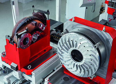
The engineering answer lies in a dedicated Stationary Part Machining Center. By clamping the heavy or complex part firmly to a rigid, stationary indexing rotary table while moving the cutting tool through synchronized U-axis toolhead interpolation, manufacturers achieve complete spherical, conical, facing, threading, and boring geometries with zero rotational mass penalty.
2. Kinematic & Structural Architecture of Stationary Machining Centers
A true stationary part machining center is not merely a conventional 4-axis Horizontal Machining Center (HMC) with a facing head attachment. It represents a ground-up kinematic redesign of machine tool structures engineered specifically for static rigidity and high dynamic precision under variable cutting loads.
2.1 High-Damping Meehanite Cast Iron Bed & Column Construction
At Nanjing Fortis Storage Equipment Manufacturing Co., Ltd., machine structures utilize heavy Meehanite process class cast iron frames featuring wide, hand-scraped linear or box guideways. The structural mass distribution absorbs heavy interrupted cutting forces generated during tough metal removal in nickel alloys (Inconel 718, Duplex 2205) and forged carbon steel.
2.2 Stationary Table Stability vs. Dynamic Pallet Indexing
Instead of driving a massive workpiece through high-speed rotation, the stationary machining center utilizes a high-precision B-axis rotary table driven by direct-drive torque motors or dual-worm gear arrangements with hydraulic mechanical clamping. Key advantages include:
- Unlimited Workpiece Weight Thresholds: Table load capacities exceeding 20,000 kg without affecting spindle rotational accuracy.
- Zero Centrifugal Inertia: High cutting speeds are achieved at the tool slide rather than the fixture, ensuring smooth tool interaction regardless of part symmetry.
- Integrated Hydraulic Fixturing: Simplifies automatic clamp/unclamp sequences directly integrated with standard PALLET changer systems (FMS).
3. Dual-Spindle & U-Axis Facing Head Mechanics
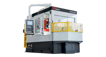
The definitive technological cornerstone of the stationary part machining centers engineered by Nanjing Fortis Storage Equipment Manufacturing Co., Ltd. is the Dual-Spindle Headstock Design with an integrated U-Axis Contouring Facing Head.
3.1 Dual-Spindle Functionality: Quill Milling & U-Axis Turning
Unlike conventional single-spindle centers that rely on detachable outer facing heads (which compromise torque transmission and tool changer capacity), our specialized horizontal U-axis architecture features two separate, harmonized mechanical drives within a single headstock housing:
- The Heavy-Duty Milling Quill Spindle: A dedicated, high-torque or high-RPM spindle engineered for aggressive face milling, end milling, deep-hole drilling, and rigid tapping operations.
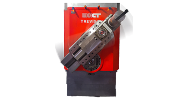
- The Integrated U-Axis Facing Head Spindle: A continuous-duty rotating facing head featuring an integrated radial cross-slide (U-axis). As the facing head rotates, the CNC controller dynamically interpolates the U-axis tool slide stroke, enabling real-time contour turning, taper facing, single-point threading, and complex internal chambering.
3.2 Single-Point Turning on a Non-Rotating Workpiece
How does a stationary part machining center generate true turning surfaces? The U-axis slide carries standard lathe tooling (e.g., ISO turning inserts). As the main head rotatably drives the tool at programmed surface speeds ($Vc$), the numerical controller commands the U-axis stroke radial distance ($R$). By coupling the U-axis movement with linear feed axes (X, Y, Z), the machine executes complete turning cycles:
- Complex Spherical Valve Seats: Interpolating U and Z axes creates perfect micro-finished metal-to-metal valve ball sockets without specialized form tools.
- Phonographic Serrated Flange Facing: Generating precise spiral grooves across ANSI/ASME flange faces in a single continuous movement.
- Tapered Pipe Threading (API Spec 5B): Cutting internal and external tapered threads with precise single-point inserts.
4. Financial ROI & Total Cost of Ownership (TCO) Analysis
For B2B procurement managers evaluating capital equipment expenditures ($CAPEX$), machine purchase decisions are ultimately measured against unit cost reduction, scrap elimination, labor optimization, and overall floor space footprint ($OPEX$).
Request a Custom Engineering ROI & Setup Study
Send your CAD models or component blueprints to our technical application engineers for a comprehensive cycle time and cost analysis.
4.1 The Setup Consolidation Multiplier
Traditional manufacturing of a large valve housing or fluid end casting requires a multi-machine line sequence:
Op 10: VTL Face & Turn side A → Op 20: Crane transfer to VTL side B → Op 30: Crane transfer to 4-Axis HMC for flange bolt holes → Op 40: Manual deburring & inspection.
In contrast, a Stationary Part Machining Center executes all operations in a Single Setup (Op 10 Done-In-One):
Op 10: Clamp once on B-axis table → U-axis turns all internal/external seal faces → B-axis indexes 90° → Quill spindle mills pockets and drills bolt patterns → Complete part unclamp.
4.2 Quantifiable Cost-Savings Breakdown
- 65% Reduction in Floor-to-Floor Cycle Time: Eliminating overhead crane wait times, fixture alignment sequences, and intermediate inspection steps.
- Preservation of True Geometric Tolerances (GD&T): Because the workpiece remains clamped on a single datum, concentricity, perpendicularity, and true position errors between turned seal faces and milled bolt holes are virtually zero ($\le 0.005 \text{ mm}$).
- 70% Floor Space Reduction: Replacing two VTLs and one horizontal machining center with a single stationary part machining cell.
- Tooling Expense Optimization: Single-point U-axis turning uses standard $15 carbide inserts instead of custom $3,000 solid form-milling cutters.
5. Cross-Industry Applications & Case Studies
5.1 Oil & Gas Flanges, Valves & Subsea Trees
Components such as Christmas tree valve blocks, large gate valves, and blowout preventers demand 100% pressure-tight metal-to-metal sealing surfaces. Thermal growth or vibration marks from conventional turning cause high scrap rates. Stationary part machining centers deliver smooth, mirror-finish seat contours ($Ra < 0.2 \mu m$) directly inside deep internal cavities.
5.2 Aerospace Structural Castings & Turbine Housings
Thin-walled aluminum or titanium aerospace housings deform under high clamping pressures necessary to hold parts on spinning lathe chucks. A stationary setup permits low-clamping-force vacuum or hydraulic dedicated tombstone fixtures, preventing part distortion during milling and turning cycles.
5.3 Heavy Equipment, Ag & Construction Axles
Cast iron axle housings and transmission casings feature wide-offset geometries that are physically impossible to swing on a lathe swing diameter without striking machine guards. Stationary part machining handles unlimited swing envelopes defined solely by axis stroke lengths (X, Y, Z travel).

6. Empirical Comparison Matrix
The following technical evaluation matrix compares key performance metrics of Stationary Part Machining Centers against Vertical Turning Lathes (VTL) and Conventional 5-Axis Horizontal Machining Centers.
| Performance Metric | Stationary Part Center (U-Axis) | Vertical Turning Lathe (VTL) | Conventional 5-Axis HMC |
|---|---|---|---|
| Part Motion Principle | Workpiece Static / Tool Rotates & Interpolates | Workpiece Rotates High-RPM / Tool Static | Workpiece Rotates/Tilts / Tool Rotates |
| Dynamic Imbalance Risk | Zero (No rotational mass) | High (Out-of-balance forces) | Moderate to High |
| Setup Requirements | Single Setup (Op 10 Complete) | Multiple Setups + Transfer to HMC | Single to Double Setup |
| Contour Turning Capability | Full Real-Time U-Axis Interpolation | Standard 2-Axis Turning | Interpolated Milling (Circular Facets) |
| Surface Finish (Facing/Turning) | Exceptional ($Ra < 0.2 \mu m$) | Good ($Ra 0.8 - 1.6 \mu m$) | Segmented Mill Marks ($Ra > 1.6 \mu m$) |
| Tooling Costs | Low (Standard ISO inserts on U-slide) | Low (Standard lathe tooling) | High (Expensive custom end mills) |
| Floor Space Efficiency | High (Replaces multiple machine cells) | Low (Requires supplementary HMC) | Moderate |
7. Procurement & Engineering Evaluation Framework
When selecting a B2B supplier for stationary part machining equipment, technical evaluation teams must evaluate machine capabilities against strict geometric standards:
7.1 Key Technical Selection Parameters
- U-Axis Stroke & Maximum Facing Diameter: Verify the total radial travel of the U-slide. Standard systems range from 100 mm up to 1,000 mm facing diameter.
- Spindle Torque Curves: Ensure high torque availability at low RPM for heavy turning in nickel alloys (e.g., > 1,500 Nm torque ratings).
- Thermal Compensation Systems: Look for direct scale feedback (Heidenhain optical linear scales) on X, Y, Z, and U axes with cooling jacket fluid circulation around headstock bearings.
- Pallet System Integration: Assess compatibility with fast shuttle pallet changers or automated linear palletech systems for unmanned 24/7 operations.
8. Company Profile & Enterprise Capability
Nanjing Fortis Storage Equipment Manufacturing Co., Ltd. is a global leader in designing, engineering, and manufacturing world-class CNC machining centers. Backed by over six decades of continuous machine tool innovation, our products serve demanding industrial applications across 100+ countries.
Our Core Competencies:
- Integrated Facing Head Mastery: Pioneers in horizontal U-axis dual-spindle designs eliminating secondary lathe operations.
- Customized Application Engineering: Full turnkey line development, including dedicated fixtures, custom tooling packages, and optimized CNC programming.
- Global After-Sales & Lifetime Technical Support: On-site commissioning, maintenance contracts, quick-dispatch spare parts, and comprehensive operator training programs.
9. Frequently Asked B2B Technical Questions (AI Intent FAQ)
The workpiece is locked securely in place on the machine's rotary indexing table. Turning is accomplished via an integrated U-axis facing head spindle. The head rotates the turning insert around the fixed part while the numerical controller continuously adjusts the radial position of the U-axis tool slide. This allows the tool to turn internal/external diameters, taper faces, seal grooves, and threads without spining the component itself.
Add-on facing heads are secondary attachments mounted via tool changers. They lack static rigidity, limit allowable RPM, restrict torque transfer, and take up tool magazine space. A dedicated dual-spindle design integrates both high-power milling quill and dynamic U-axis facing head directly into the main cast iron headstock housing, supplying high rigidity, maximum drive torque, and full automatic tool changer compatibility.
Yes. Because all facing, turning, boring, milling, and drilling operations are executed in a single setup on one master datum scheme, error accumulation caused by releasing, re-clamping, and recalibrating parts between multiple machines is completely eliminated. Concentricity between turned features and true position of milled patterns are kept under 0.005 mm.
Our machining centers support standard heavy-duty tooling interfaces, including ISO 50, BT50, CAT50, and HSK-A100 spindle tapers. Custom heavy U-axis tool slides accept standard cartridge turning toolholders, enabling easy integration with your existing tooling inventory.
You can contact our sales engineering department directly by emailing [email protected] or submitting your CAD part models via our online contact form. Our application engineering team will provide a comprehensive cycle-time analysis, fixture concept study, and quotation tailored to your production volume.
Partner with Nanjing Fortis Storage Equipment Manufacturing Co., Ltd.
Upgrade your heavy manufacturing operations with market-leading stationary part machining centers engineered for maximum uptime and precision performance.