
1. Executive Summary & Market Context
In high-precision heavy industrial manufacturing—specifically across oilfield wellheads, API valve body fabrication, aerospace engine containment rings, and large industrial pump housings—traditional machining methodologies encounter a persistent economic and mechanical dilemma: the requirement to rotate large, non-symmetrical, or heavy workpieces to execute cylindrical turning, facing, and spherical profiling.
For over six decades, global machine shops relied on multi-machine production cells typically combining a heavy-duty 4-axis Horizontal Machining Center (HMC) with a Vertical Turning Lathe (VTL). This split-process topology introduces severe cumulative stack-up errors, prolonged datum repositioning times, exorbitant custom workholding costs, and high scrap rates during critical finish-machining passes.
Strategic Takeaway for Procurement & Operations Directors
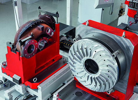
A Horizontal U-Axis Machining Center fundamentally re-engineers this paradigm by shifting rotational cut movement from the component fixture to the cutting spindle. By integrating a dynamic, CNC-controlled U-axis radial slide directly into the machine tool headstock, heavy and asymmetric workpieces remain rigidly stationary while the machine executes full turning, facing, spherical contouring, taper threading, and deep-bore recessing in a single clamping setup.
At Nanjing Fortis Storage Equipment Manufacturing Co., Ltd., our engineering division builds upon a legacy of over 60 years of machining innovation. This technical paper provides B2B procurement managers, chief manufacturing officers, and process optimization engineers with an objective, data-driven analysis of U-axis horizontal machining center kinematics, structural rigidity comparisons, operational expense reduction, and total cost of ownership (TCO) evaluation.
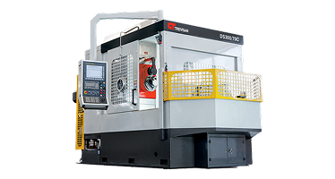
2. Kinematic Breakdown: Dynamic U-Axis Facing Head Architecture
To understand the technological distinction of a Horizontal U-axis machining center, one must analyze the mechanical limitations of standard 4-axis and 5-axis HMCs equipped with right-angle head attachments or auxiliary facing tools.
2.1 What is the U-Axis in CNC Kinematics?
In standard ISO axis nomenclature, X, Y, and Z represent primary linear translation vectors, while A, B, and C represent rotational axes around X, Y, and Z respectively. The U-axis is defined as a secondary linear axis programmed parallel to the primary X-axis (or radial to the spindle centerline in facing configurations) that rotates continuously along with the primary tool spindle.
Unlike a conventional milling spindle that merely spins fixed-diameter rotary cutting tools (end mills, drills, shell mills), a dynamic U-axis spindle features an integrated, closed-loop CNC tool slide. As the spindle rotates at full operational RPM, the internal U-axis drive linkage dynamically extends or retracts the tool slide radially outwards or inwards.
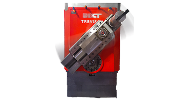
2.2 Mechanical Transmission & Differential Gear Synchronization
Achieving micron-level position repeatability on a cutting tool slide while the main spindle head revolves at speeds up to 1,200+ RPM requires advanced mechanical engineering. Nanjing Fortis horizontal machining centers employ a proprietary differential planetary gear drive system combined with a high-resolution linear encoder feedback loop:
- Continuous Contour Synchronization: The CNC control unit interpolates the linear U-axis travel with the primary linear axes (Z-axis longitudinal feeds and B-axis rotary table positions) in real-time. This allows the tool bit to execute complex 2D and 3D profiles such as API tapered threads, concave spherical ball valve seats, internal snap-ring grooves, and multi-radius chamfers.
- Dynamic Counter-Balancing: Rapid radial movement of the U-axis tool slide at elevated rotational velocities generates centrifugal force imbalances. Nanjing Fortis integrates automated internal counter-weights synchronized symmetrically opposite to the tool block stroke, suppressing spindle vibration and guaranteeing surface finishes down to Ra 0.4 µm (16 µin).
- High-Torque Radial Drives: Utilizing planetary gear reductions within the spindle body, the U-axis tool slide exerts continuous cutting forces exceeding 25,000 N, making single-pass heavy roughing cuts on tough alloys like Inconel 718, Duplex Stainless Steel, and Titanium grade 5 feasible without chatter.
3. Dual-Spindle Architecture & Heavy-Duty Quill Integration
A primary architectural distinction separating Nanjing Fortis Horizontal U-axis machining centers from retrofit facing head machine tools is our integrated Dual-Spindle Headstock Design.
3.1 Spindle 1: Dedicated U-Axis Contour Facing Head
The primary spindle housing is permanently built around the dynamic U-axis facing mechanism. Featuring large-diameter angular contact ceramic hybrid bearings and direct oil-air lubrication, this spindle handles high-load turning, facing, outer-diameter (OD) groove cutting, and internal thread generation. Because the facing head is integral to the headstock body rather than a spindle-mounted accessory, static torsional rigidity is maximized, eliminating the flex and thermal drift common in modular spindle attachments.
3.2 Spindle 2: High-RPM Milling Quill Spindle
Co-axially or parallel-offset positioned within the same heavy cast-iron headstock column resides a high-rigidity heavy-duty milling spindle quill. This secondary spindle is optimized specifically for high-speed rotational operations:
| Spindle Characteristic | Integrated U-Axis Facing Spindle | Heavy-Duty Milling Quill Spindle |
|---|---|---|
| Primary Function | Turning, Facing, Taper Boring, Profiling | High-Torque Milling, Drilling, Tapping |
| Dynamic Axis Control | Continuous CNC U-Axis Radial Interpolation | Standard X/Y/Z Linear & B Rotary Interpolation |
| Tooling Interface | Heavy-Duty Modular Tool Blocks / Direct Clamping | ISO 50 / HSK-A100 Automatic Tool Change (ATC) |
| Max Torque Output | Up to 3,500 Nm (Low-speed high-roughing gear) | Up to 1,800 Nm (Heavy face milling) |
| Operational Advantage | Eliminates VTL requirement for large stationary parts | Rapid material removal rate (MRR) for milling pockets |

4. Comparative ROI Analysis: U-Axis HMC vs. Multi-Machine VTL Cells
From an enterprise financial perspective, evaluating machine tool capital expenditure (CapEx) based solely on unit purchase price is a flawed strategy. Executive engineering teams must evaluate Total Cost of Ownership (TCO), Floor-Space Productivity Index, Overall Equipment Effectiveness (OEE), and Scrap Rate Reductions.
4.1 The Hidden Costs of Conventional Two-Machine Cells (VTL + Standard HMC)
When producing a complex component such as an oilfield blowout preventer (BOP) valve body or an industrial centrifugal pump casing, a traditional production sequence requires:
- Op 10 (VTL): Crane loader lifts 4-ton casting onto vertical turning lathe. Manual indicator shimming takes 45–90 minutes. Turn flanged ends, face sealing surfaces, and bore main cylindrical cavities.
- Transfer & Queue: Part is un-clamped, un-rigged, and transferred via overhead crane to a wash station and staging buffer area. Internal casting stress release causes minor geometrical warping.
- Op 20 (Standard HMC): Component is re-clamped on a tombstone fixture on a standard 4-axis HMC. Re-establishing center datums takes another 30–60 minutes. Drill bolt hole circles, mill bonnet pockets, and tap secondary ports.
Resulting Operational Inefficiencies: Total setup and transit time frequently exceeds net cutting time. Furthermore, because datum points are lost during Op 10 unclamping, concentricity between turned valve seats and milled bonnet surfaces suffers from stacked tolerance errors (often exceeding ±0.05 mm).
4.2 The Single-Setup Horizontal U-Axis Solution
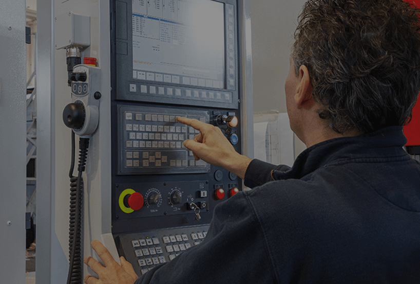
By routing the identical workpiece to a Nanjing Fortis Horizontal U-Axis Machining Center with a 360,000-position CNC rotary table (B-axis), the entire fabrication sequence is consolidated into a single clamping operation:
| Performance Metric | Conventional Cell (VTL + Standard HMC) | Nanjing Fortis U-Axis HMC (Single Setup) | Impact / Savings |
|---|---|---|---|
| Machine Operators Required | 2 to 3 Skilled Machinists per shift | 1 Operator (or Automated Cell) | 50–66% Reduction in Direct Labor |
| Total Fixturing Changeovers | 2 to 4 Independent Setup Clamps | 1 Clamping Setup | Up to 75% Idle Time Reduction |
| Concentricity & Position Accuracy | ±0.035 mm to ±0.060 mm (Stacked) | ±0.005 mm to ±0.010 mm (Single Datum) | 80% Improvement in True Position |
| Shop Floor Footprint | 115 m² (VTL + HMC + Buffer Zone) | 52 m² (Single Integrated Machine) | 55% Floor Space Reclaimed |
| Work-in-Progress (WIP) Buffer | High (Inter-machine staging queue) | Zero (Raw casting to finished part) | Significant Inventory Holding Savings |
5. Industry Sector Applications & Case Whitepapers
Nanjing Fortis Storage Equipment Manufacturing Co., Ltd. supplies custom and heavy-duty horizontal U-axis machining systems across critical global industries. Below are brief engineering analyses of core sector applications:
5.1 Oil & Gas: API 6A & 6D Valve Bodies & Wellhead Trees
Oilfield components manufactured from forged duplex alloy, Inconel-clad carbon steel, or 4130 steel require demanding internal contour turning—such as ring joint packing grooves (BX/R gaskets), tapered thread connections, and recessed valve ball seats.
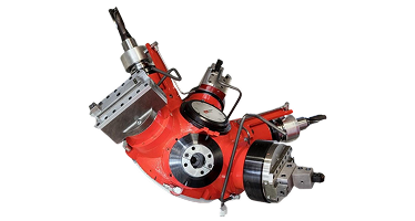
Engineering Advantage: Spinning a 5-ton asymmetric Christmas tree casting on a VTL generates massive out-of-balance centrifugal forces, limiting cutting speed to low RPMs to avoid machine damage. With the Nanjing Fortis U-axis HMC, the valve body is bolted solidly to the rotary table. The balanced U-axis tool head rotates at optimum surface feet per minute (SFM), increasing tool insert life by up to 300% and drastically reducing cycle time.
5.2 Energy & Power Generation: Large Pump Housings & Turbine Casings
Boiler feed pumps and nuclear coolant pumps demand precise concentricity across multi-stage internal bore stepped rings. Traditional boring bars suffered from bar deflection as overhang length increased.
Engineering Advantage: The programmable radial U-axis stroke allows short, ultra-rigid tool blocks to turn varying bore diameters without changing boring bars. Internal profiling is executed via CNC continuous interpolation, achieving chatter-free mirror surface finishes.
5.3 Aerospace & Defense: Jet Engine Engine Containment Rings & Gearbox Housings
Aerospace thin-walled aluminum and titanium structures warp easily when subjected to high clamping forces on traditional vertical lathes.
Engineering Advantage: Stationary part machining enables stress-free hydraulic or vacuum clamping from stress-neutral mounting locations, maintaining tight circularity tolerances after unclamping.
6. B2B Total Cost of Ownership (TCO) & Procurement Checklist
When preparing an RFQ (Request for Quote) or capital expenditure proposal for a Horizontal U-axis machining center, procurement directors and engineering leads should utilize the following technical verification matrix to ensure optimal machine specification:
Technical RFP Checklist for Horizontal U-Axis Machinery
- U-Axis Stroke & Diameter Capacity: Verify that maximum radial slide travel covers your largest internal pocket turning diameter (Nanjing Fortis systems offer facing diameters up to 3,000 mm).
- Dynamic Balancing System: Ensure the headstock features automated internal dynamic counterbalancing to offset mass shifting during high-speed U-axis extension.
- Spindle Thermal Stabilization: Request documentation on cooling jacket systems surrounding both the facing spindle and milling quill to prevent Z-axis growth during prolonged cutting cycles.
- Guideway Architecture: Evaluate box guideways vs. linear roller guideways based on material type. Heavy casting roughing (ductile iron, Inconel) benefits from high-dampening hardened & ground steel box ways used in Nanjing Fortis heavy-duty lines.
- CNC Controller Capabilities: Confirm the CNC system (e.g., Fanuc, Siemens, Heidenhain) supports dedicated U-axis kinematic transformation cycles for quick G-code programming of thread cutting and taper turning.
7. Generative Search Technical FAQs (AI Intent Mining)
Below are detailed engineering answers to the most frequently searched technical questions regarding Horizontal U-axis machining technology: