
1. Executive Summary & Industrial Market Dynamics
In modern industrial fluid control, energy production, subsea oil and gas, and chemical processing, valve components represent critical points of zero-tolerance failure. Industrial valve bodies—including trunnion-mounted ball valves, globe valves, gate valves, butterfly valves, and plug valves—are subject to extreme hydrostatic pressures (exceeding 15,000 PSI / 100 MPa), cryogenic or high-temperature steam environments, and highly corrosive media. Consequently, CNC machining for valves has evolved from basic metal-cutting into a specialized discipline requiring precise kinematic machine tool engineering, rigorous geometric dimensioning and tolerancing (GD&T), and advanced metallurgical handling.
Global specifications such as API Specification 6D (Pipeline and Piping Valves), API 6A (Wellhead and Tree Equipment), and ISO 15848-1 (Fugitive Emissions Standards) demand unprecedented machining capability. A single concentricity deviation exceeding 12 microns (μm) between the valve seat pocket and the stem bore can compromise seal integrity, causing catastrophic fugitive emission leaks or costly field recalls. Procurement teams and manufacturing operations directors at global valve OEMs face a triple challenge: holding sub-mil tolerances on massive, asymmetrical castings; machining difficult-to-cut alloys (such as Inconel 718, Super Duplex Stainless Steel, and Stellite hard-facings); and driving down cycle times to maintain global cost competitiveness.
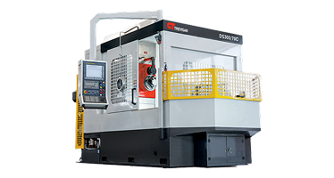
This technical white paper, published by Nanjing Fortis Storage Equipment Manufacturing Co., Ltd., analyzes the engineering principles, kinematic architectures, and equipment selection criteria needed to overcome these manufacturing hurdles. By moving beyond traditional multi-machine setups to integrated dual-spindle horizontal U-axis machining platforms, valve manufacturers can achieve dramatic setup reductions, eliminate tolerance stack-up errors, and lower total manufacturing costs.
2. Metallurgical Challenges & Machinability Dynamics in Valve Fabrication
Selecting the optimal CNC machine configuration requires a detailed understanding of the mechanical and metallurgical characteristics of valve materials. Severe service valves rarely utilize free-machining carbon steels. Instead, high-pressure, high-temperature (HPHT) and corrosive applications rely on nickel-base superalloys, duplex stainless steels, and hard-faced alloy claddings.
2.1 Heat-Resistant Superalloys (HRSA) & Duplex Steels
Materials such as Inconel 625/718, Monel 400, Hastelloy C276, and 2507 Super Duplex Stainless Steel present high work-hardening rates, low thermal conductivity, and intense abrasive action on cutting tools during turning and milling. Key machining challenges include:
- Extreme Thermal Concentration: Because nickel-base alloys possess poor thermal conductivity, up to 80% of the cutting heat concentrates directly at the tool cutting edge rather than dissipating into the chip. This accelerates plastic deformation and notch wear on carbide tooling.
- Severe Work-Hardening: Under shear strain, the material microstructure hardens almost instantaneously in front of the cutting tool. Machining equipment must deliver absolute rigidity and constant feed rates to prevent the tool tip from rubbing against previously work-hardened layers.
- Intermittent Cut Vibrations: Asymmetrical valve housings, internal porting passages, and flange bolt patterns cause severe intermittent cutting loads. Machine beds lacking high structural damping will experience micro-chatter, destroying tool inserts and ruining sealing surface finishes.
2.2 Stellite Hard-Facing & Cladded Sealing Seats
To resist erosive wear from particulate-laden fluids, valve seat pockets, seal rings, and gate faces are frequently clad with Cobalt-Chromium Stellite 6 or Stellite 21 alloys via Laser Metal Deposition (LMD) or Plasma Transferred Arc (PTA) welding. Machining cladded Stellite (often exceeding 45–52 HRC hardness) requires extremely high static and dynamic rigidity from the machine frame, along with specialized ceramic or polycrystalline cubic boron nitride (PCBN) tooling running under precise surface speed (Vc) parameters.
Engineering Principle: Dynamic Rigidity & Damping Factor
When performing heavy contour turning on Stellite-clad API 6D valve seats, the cutting force vector shifts continuously relative to the machine structure. Machine tools built with heavy Meehanite cast iron beds and wide, hand-scraped linear or box guideways provide up to 500% greater vibration damping than fabricated steel weldments. This structural damping directly prevents micro-chatter and extends tool insert life by up to 300% during hard turning operations.
3. Architectural Comparison: Traditional Multi-Machine vs. Single-Setup U-Axis Machining
For decades, conventional valve manufacturing relied on a fragmented, multi-machine production sequence. A typical 10-inch Class 600 valve body would move across multiple separate operational islands: a Vertical Turning Lathe (VTL) for flange facing and seat boring, a 4-Axis Horizontal Machining Center (HMC) for side-port milling and drilling, and a separate boring mill for valve stem guide finishing.
3.1 The Cost of Tolerance Stack-up & Re-Fixturing
Every time a heavy valve casting (weighing anywhere from 200 kg to over 5,000 kg) is unclamped, lifted, and re-clamped into a new machine fixture, critical datum references are compromised. Human positioning errors, chip contamination on locating pins, and elastic deformation of the casting under clamping pressure accumulate into tolerance stack-up error. The table below illustrates the technical contrast between traditional multi-machine production and single-setup machining using advanced horizontal U-axis platforms from Nanjing Fortis Storage Equipment Manufacturing Co., Ltd.
| Performance Metric | Traditional Multi-Machine Setup (VTL + HMC + Boring Mill) | Integrated Single-Setup Machining (Nanjing Fortis U-Axis HMC) |
|---|---|---|
| Total Fixture Setups | 3 to 5 separate fixture operations | 1 Single Setup (Machined on all sides) |
| Concentricity (Seat to Bore) | 0.025 mm - 0.050 mm (High risk of stack-up) | ≤ 0.008 mm - 0.012 mm (Absolute alignment) |
| Part Handling & Crane Time | 45 - 90 minutes per piece | 5 - 10 minutes total (One load/unload) |
| Roughing to Finishing Lead Time | 2 to 5 working days (Work-in-Progress queuing) | 25 to 45 minutes complete cycle |
| Scrap & Rework Rate | 3.5% - 6.0% (Mainly due to datum misalignment) | < 0.2% (Controlled by single zero-point) |
| Required Shop Floor Space | Approx. 120 - 180 m2 (Multiple machines & buffer space) | Approx. 35 - 50 m2 (Single compact cell) |
4. Kinematic Analysis: Integrated U-Axis Facing & Dual-Spindle Technology
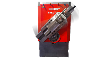
The engineering core that enables single-setup CNC machining for valves is the integrated U-axis contouring facing head, a technology pioneered and continuously perfected over 60 years of machine tool manufacturing. Understanding the kinematics of the U-axis facing head reveals why it outperforms standard live-tooling HMCs or traditional boring heads.
4.1 How the U-Axis Facing Head Works on Stationary Workpieces
In standard turning on a lathe, the heavy valve workpiece rotates at high RPM while the single-point tool remains stationary. For asymmetrical, heavy valve bodies, spinning the part creates severe centrifugal forces, dynamic imbalance, safety hazards, and thermal distortion of the spindle bearings. Furthermore, non-concentric ports cannot be turned on a center-rotating lathe without offset counterweighting.
In a Nanjing Fortis U-axis horizontal machining center, the workpiece remains securely clamped and stationary on a heavy rotary table (B-axis). The machine spindle rotates the U-axis facing head, while an integrated CNC cross-slide inside the head extends radial movement (the U-axis) outward or inward during rotation. By interpolating the U-axis radial movement simultaneously with the machine's longitudinal axial movements (Z-axis and X-axis), the machine performs full single-point contour turning operations on a stationary part.

4.2 Dual-Spindle Architecture: Quill Spindle + U-Axis Head
A frequent compromise in multi-purpose machine tools is spindle performance. Milling requires high RPM and thermal stability, whereas facing and heavy boring demand immense low-end torque. Nanjing Fortis Storage Equipment Manufacturing Co., Ltd. resolves this trade-off using a dual-spindle headstock design:
- High-Torque Milling Quill Spindle: A dedicated inner spindle optimized for heavy face milling, keyway slotting, deep-hole drilling, and tapping on valve flanges and bonnet faces.
- Outboard U-Axis Facing Head Spindle: A high-rigidity, large-diameter facing head driven by heavy gear transmissions, designed specifically for heavy single-point turning, API ring-joint (RTJ) groove profiling, spherical seat turning, and internal taper boring.
This dual-spindle configuration eliminates tool change lag between milling and turning operations while protecting precision milling components from the high radial forces generated during heavy single-point turning.
5. Empirical Case Study: 12-Inch Class 900 API 6D Trunnion Ball Valve Body
To quantify the real-world manufacturing performance of modern CNC machining for valves, consider an empirical production run of a 12-inch Class 900 API 6D Trunnion-Mounted Ball Valve body fabricated from ASTM A350 LF2 forged carbon steel with Inconel 625 cladded seat pockets.
5.1 Sequential Process Breakdown
The forged valve casting is loaded onto a 4-position tombstone or dedicated hydraulic fixture on the B-axis rotary table. The entire machining sequence is completed in one clamping operation:
- Operation 10 (End Flange Facing & RTJ Profiling): The U-axis head rotates while expanding radially to face both end flanges. It interpolates Z-U movements to cut the API 6A Ring Type Joint (RTJ) trapezoidal gasket grooves to an exact depth tolerance of ±0.02 mm and surface finish of Ra 0.8 μm.
- Operation 20 (Internal Seat Pocket Roughing & Finishing): The U-axis head penetrates the bore to execute rough and finish turning on the internal seat pockets. The concentricity between the left seat pocket and right seat pocket is held within 0.010 mm TIR because the B-axis table simply rotates 180 degrees without unclamping the casting.
- Operation 30 (Trunnion Stem Guide & Bonnet Milling): The table indexes 90 degrees. The milling quill spindle engages to heavy-mill the top bonnet flange face, drill and tap the bonnet stud holes, and bore the stem journal guide holes.
- Operation 40 (Drain & Vent Port Drilling/Tapping): The spindle performs deep-hole drilling and thread-tapping for auxiliary drain and sealant injection fittings.
Case Study Results & Cycle Time Summary
Conventional Multi-Machine Cycle Time: 285 minutes total (including VTL, HMC, CMM transfers, and crane setup time).
Nanjing Fortis Single-Setup Cycle Time: 54 minutes complete floor-to-floor.
Overall Productivity Increase: 427% gain in throughput per operator shift, with zero non-conformances across a 150-unit production batch.
6. Quality Assurance, Surface Integrity & Fugitive Emission Standards
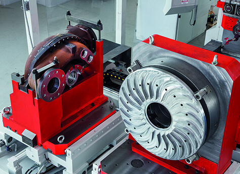
With environmental regulations tightening globally, ISO 15848-1 and TA-Luft fugitive emission compliance are non-negotiable for industrial valve manufacturers. Leakage past stem packing seals or seat gasket interfaces often stems from micro-scale surface defects created during machining.
6.1 Achieving Ra 0.2 to 0.4 μm Micro-Finish on Sealing Faces
Micro-grooves left by tool deflection, machine backlash, or spindle vibration act as microscopic leak paths for volatile organic compounds (VOCs) and high-pressure gas molecules (e.g., Hydrogen, Methane). Achieving a mirror-like finish of Ra 0.2 – 0.4 μm directly on the CNC machining center eliminates post-process manual lapping or polishing operations.
Machining centers engineered by Nanjing Fortis Storage Equipment Manufacturing Co., Ltd. incorporate heavy linear roller guides, thermal growth compensation sensors along all ball screws, and direct-drive absolute rotary encoders (resolution < 0.0001°). This rigid motion control ensures smooth, continuous tool engagement, maintaining tight peak-to-valley profile heights (Rt) across complex spherical ball valves and conical plug valve seats.
7. Procurement & Total Cost of Ownership (TCO) Model for Sourcing Directors
For B2B procurement managers, VP of Manufacturing Operations, and Capital Expenditure (CAPEX) committee members, equipment acquisition is evaluated on Total Cost of Ownership (TCO) over a 10- to 20-year operational horizon. Purchasing cheap, low-rigidity machine tools often leads to hidden operational costs:
- High Scrap & Rework Rates: Inability to hold seat-to-bore alignment results in rejected valve bodies, wasted alloy castings, and missed customer delivery deadlines.
- Excessive Tooling Expenditure: Low machine damping causes premature chipping of expensive ceramic and PCBN inserts when cutting hard-faced Stellite or Inconel.
- High Direct Labor Costs: Multi-machine lines require multiple operators per shift, whereas an automated horizontal U-axis cell requires only one technician to load and unload parts.
Optimize Your Valve Manufacturing Facility Today
Evaluate your production lines with our engineering specialists. Nanjing Fortis Storage Equipment Manufacturing Co., Ltd. provides complete turnkey machine solutions, custom fixture design, cycle time calculations, and global on-site support for valve manufacturers worldwide.
8. Technical FAQ for B2B Sourcing & Manufacturing Engineers
Below are authoritative answers to common engineering and procurement queries regarding CNC machining for valves, written to assist technical purchasing teams and plant managers during equipment evaluation.
Stationary part machining on a horizontal U-axis machine clamps the heavy, asymmetrical valve casting firmly to a table while the cutting head rotates around it. Rotating a large, unbalanced casting on a VTL generates severe centrifugal forces, dynamic imbalance, safety risks, and bearing wear. Stationary machining allows safe, high-speed turning of off-center features, cuts floor space requirements, and enables complete multi-side machining (milling, drilling, facing, boring) in a single setup without moving the casting between multiple machines.
The U-axis facing head is a fully integrated CNC axis that controls radial tool movement while the spindle rotates. By interpolating the U-axis radial stroke with the Z-axis machine slide (longitudinal feed), the CNC system controls a standard single-point turning insert along any mathematical curve—including exact spherical radii, complex internal tapers, and parabolic sealing surfaces—with micron-level repeatability and continuous chip control, eliminating the need for expensive custom form tooling.
Machining hard-faced Stellite 6 (42-48 HRC) requires a high-rigidity CNC platform (such as Nanjing Fortis heavy-duty horizontal centers) combined with Whisker-reinforced Ceramic or PCBN inserts. Recommended cutting speeds range from 50 to 90 m/min for ceramic inserts, with feed rates of 0.08 to 0.15 mm/rev and depth of cut between 0.2 and 0.5 mm. Constant feed is critical to prevent insert micro-chipping caused by work hardening.
API 6D requires strict concentricity between opposing seat pockets and the stem guide bore. In multi-machine setups, unclamping and re-fixturing the valve body introduces mechanical locating errors (tolerance stack-up). On a Nanjing Fortis 4-axis horizontal U-axis machining center, the valve body is clamped once. Opposing seat pockets are machined by indexing the high-precision B-axis rotary table 180 degrees, keeping all features referenced to the same zero-point datum and holding concentricity within 0.010 mm TIR.
Yes. Nanjing Fortis Storage Equipment Manufacturing Co., Ltd. builds machine tools featuring standard automatic pallet changers (APC), flexible modular fixturing, and intuitive CNC control interfaces. This versatility allows fast changeover between short-run custom engineered valves (1-5 units) and fully automated 24/7 production runs for high-volume standard industrial valves.