
Executive Summary: Information Gain for B2B Procurement
Modern heavy component manufacturing across oil & gas, aerospace, energy, and heavy hydraulics faces a fundamental economic bottleneck: conventional production routes rely on sequential processing across multiple discrete machine tools (e.g., Vertical Turning Lathes for turning and facing, paired with Horizontal Machining Centers for milling, drilling, and tapping). This multi-machine dependency introduces compounding tolerance stackup, excessive crane repositioning, prolonged setup lead times, and inflated floor space requirements.
This white paper authored by Nanjing Fortis Storage Equipment Manufacturing Co., Ltd. details how a purpose-built Dual Spindle CNC Machine incorporating a dedicated heavy-duty milling quill spindle alongside an integrated CNC U-axis contour facing head revolutionizes heavy part fabrication. By completing complex turning, spherical facing, tapering, boring, milling, and threading operations on stationary workpieces in a single clamping setup, enterprise manufacturers routinely realize cycle time compression between 45% and 65% while reducing direct manufacturing overhead by over 50%.
2. The Multi-Op Manufacturing Dilemma: Why Conventional Workflow Fails
When producing large industrial components—such as oilfield blowout preventers (BOPs), gate valve bodies, pump casings, or agricultural gear housings—manufacturing engineers traditionally face a dilemma. These components possess complex internal geometries requiring high-precision concentric turning (seal seats, ring grooves, flange faces) along with extensive off-center drilling, tapping, porting, and face milling.
In a traditional manufacturing cell, the operational sequence generally follows a multi-stage path:
- Stage 1 (Turning & Facing): The component is loaded onto a Vertical Turning Lathe (VTL). The massive workpiece must be centered and clamped onto a rotating table. Facing, internal diameter boring, and flange grooves are machined.
- Stage 2 (Part Transport & Re-fixturing): An overhead crane unclamps and transfers the partially machined forging (weighing anywhere from 500 kg to over 15,000 kg) to a standard 4-axis Horizontal Machining Center (HMC).
- Stage 3 (Milling & Drilling Operations): The part is re-aligned on a tombstone or rotary table. Bolt hole patterns, auxiliary ports, flange pads, and keyways are milled and tapped.
- Stage 4 (Secondary Finish Boring): In many cases, final critical seal faces must undergo secondary finishing or manual lapping because re-clamping between VTL and HMC introduced cumulative runout errors exceeding 0.050 mm.
This conventional multi-stage approach creates severe operational friction. Every fixture transition introduces human positioning error, thermal variance, fixture deformation, and extended queue times. Furthermore, spinning asymmetrical forgings at high RPM on a lathe creates dangerous dynamic imbalances, requiring reduced cutting parameters and risking tool chatter.
3. Kinematic Architecture of Modern Dual Spindle CNC Machines
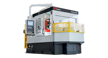
To overcome the limitations of multi-machine transfer, Nanjing Fortis Storage Equipment Manufacturing Co., Ltd. engineered a specialized horizontal machining architecture: the Dual Spindle CNC Machine with Integrated U-Axis Contouring Head.
Unlike conventional twin-spindle lathes (which utilize two opposing spindles to pass rotating parts back and forth), an industrial dual spindle horizontal machining center features two complementary cutting spindles housed within a single massive, thermally stabilized headstock casting, directed at a fixed or rotary-indexed stationary workpiece.
3.1 Dual-Spindle Headstock Mechanism Explained
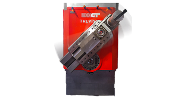
The core innovation of the dual spindle design lies in the operational division of labor between two distinct spindles integrated into one headstock:
- Spindle 1: Heavy-Duty Milling & Drilling Quill: Designed with oversized high-precision angular contact bearings, a heavy quill ram, and high torque output (up to 2,500+ Nm). This spindle handles aggressive end-milling, deep-hole drilling, tapping, and high-feed pocketing operations.
- Spindle 2: Integrated CNC U-Axis Facing & Contouring Head: A dedicated rotating spindle body carrying a radially traversing tool slide driven by a fully interpolated CNC axis (the U-axis). As the facing head rotates, the tool slide moves dynamically inward or outward under direct CNC control, executing single-point turning, conical tapering, spherical radius turning, internal chambering, and API ring-groove cutting on stationary workpieces.
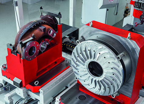
By keeping the workpiece stationary and rotating the cutting tools around the part, centrifugal forces are completely decoupled from the part mass and geometry. A 10-ton irregular valve casing can remain solidly bolted to a rigid rotary table while the U-axis facing head rotates at controlled turning speeds, achieving mirror surface finishes and sub-micron concentricity without dynamic vibration.

4. Comparative Analysis: U-Axis Facing Head vs. Turret Dual Spindles
B2B procurement teams evaluating automated CNC machinery often confuse dual-spindle turning centers (lathes with main and sub-spindles) with dual-spindle horizontal machining centers featuring integrated U-axis facing heads. The table below highlights the operational differences and performance metrics crucial for high-value B2B equipment evaluation.
| Performance / Kinematic Metric | Standard Twin-Spindle CNC Lathe | Dual Spindle HMC with U-Axis (Nanjing Fortis) |
|---|---|---|
| Workpiece Rotational Dynamics | Part rotates at high RPM (limited to symmetrical shapes) | Part remains stationary; tools rotate (handles heavy asymmetrical forgings) |
| Out-of-Round Turning Capabilities | Requires complex C-Y axis live tooling interpolation | Direct U-axis single-point turning (superior rigidity & surface finish) |
| Max Workpiece Weight Capacity | Typically limited to < 2,000 kg due to spindle overhang | Up to 20,000+ kg on heavy-duty rotary tables |
| Milling Torque & Metal Removal Rate | Limited by live-tool turret gear drive power (< 100 Nm) | Dedicated heavy-duty quill spindle (up to 3,000 Nm torque) |
| Setup Compression Factor | Requires turned blanks; poor heavy milling capability | Complete raw forging to finished part in 1 setup (100% finished) |
| Internal Chamber & Recess Turning | Difficult access; tool overhang chattering | Programmable radial U-slide access for deep internal contours |
5. Geometric Tolerance Control & Metrological Integrity
In critical fluid-handling applications (such as API 6A subsea wellhead components or nuclear grade globe valves), geometric dimensioning and tolerancing (GD&T) parameters are exceptionally stringent. Specifically, perpendicularity between the flange sealing face and the internal cylinder bore must be held within ≤ 0.012 mm, while concentricity across opposing ports must remain under ≤ 0.015 mm.
When a part is transferred between separate machines, achieving these tolerances requires laborious manual shimming, indicator alignment, and custom expensive soft jaws. Even with qualified operators, scrap rates on exotic alloys (such as Inconel 718 or Duplex 2205) can average 3% to 7% due to setup variances.
A Dual Spindle CNC Machine eliminates these failure modes through three core engineering mechanisms:
1. Single Datums Calibration
Because the part is clamped only once, all coordinate systems (X, Y, Z, B, U) share an identical, unchanged physical reference datum, eliminating zero-point shift errors entirely.
2. Thermal Symmetry Machine Bed
Heavily ribbed Meehanite cast iron beds with dual-circuit internal fluid cooling maintain structural equilibrium even during 24/7 continuous aggressive roughing cuts.
3. Closed-Loop Linear Scale Feedback
Absolute optical scales mounted on all axes provide real-time sub-micron positioning feedback to the CNC controller, neutralizing ball-screw thermal expansion.
4. Hydrostatic Guideway Damping
High dynamic damping capacity absorbs severe interrupted cutting forces when facing irregular flange surfaces or cross-bored valve ports.
6. Economic Impact Analysis & Total Cost of Ownership (TCO)
For enterprise B2B buyers, capital equipment investments must be justified through rigorous Total Cost of Ownership (TCO) and Net Present Value (NPV) modeling. Below is a comparative economic breakdown based on real-world operational data from medium-to-heavy valve manufacturing plants.
6.1 Financial Comparison: Traditional 3-Machine Cell vs. Single Dual Spindle CNC Machine
Consider a factory producing 1,200 units per year of 10-inch 5,000 PSI alloy steel gate valves.
| Cost Element / Production Variable | Legacy Cell (VTL + HMC + Boring Mill) | Dual Spindle CNC Cell (Nanjing Fortis) | Net Economic Gain |
|---|---|---|---|
| Equipment Capital Outlay (CapEx) | $1,850,000 (3 Machines) | $1,250,000 (1 Integrated Unit) | $600,000 Initial CapEx Savings |
| Required Operators per Shift | 3 Skilled Operators | 1 Operator (Cell Automation Capable) | 66% Reduction in Direct Labor |
| Total Cycle Time per Valve Body | 4.5 Hours (incl. handling & setup) | 1.8 Hours (continuous single-setup) | 60% Throughput Acceleration |
| Floor Space Requirement | 220 m² (incl. queue zones & cranes) | 95 m² (compact single-machine footprint) | 57% Floor Space Compression |
| Annual Part Scrap & Rework Cost | ~$65,000 (re-clamping runout failures) | < $5,000 (single-setup reliability) | $60,000 Direct Scrap Avoidance |
As demonstrated, substituting a fragmented multi-machine line with a single Dual Spindle CNC Machine yields full capital payback within approximately 14 to 18 months, depending on machine utilization rates and material costs.
7. Industry Application Matrix & Field Production Use Cases
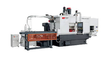
Nanjing Fortis Storage Equipment Manufacturing Co., Ltd. supplies high-rigidity CNC machining centers tailored for severe industrial environments. Below are key sector applications where dual spindle technology delivers decisive competitive advantages:
Oilfield Valve Bodies
View Technical Specs →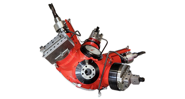
Aerospace Housings
View Technical Specs →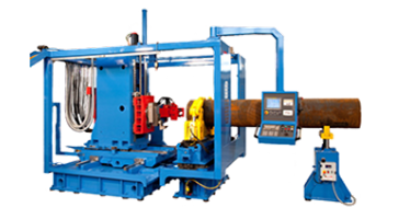
Heavy Industrial Pumps
View Technical Specs →7.1 Oil & Gas Surface & Subsea Equipment
Machining API 6A and 17D Christmas tree block valves, frac manifolds, and wellhead spools requires heavy single-point turning of internal seal grooves combined with deep stud-hole drilling. Dual spindle machines handle the entire forging in one fixture, guaranteeing perfect angular alignment between bore axes and flange bolt patterns.
7.2 Aerospace Engine Components & Gear Housings
Lightweight titanium and Inconel aerospace structures feature thin-walled geometry susceptible to clamping distortion. Stationary part dual spindle machining eliminates centrifugal wall flex while permitting high-speed milling and precision bore facing without removing the component from its stress-relieved fixture.
7.3 Energy, Power Generation & Heavy Hydraulics
Large Francis turbine hub housings, nuclear feed pumps, and agricultural tractor axle housings demand high metal removal rates alongside tight diameter tolerances. The heavy quill spindle roughs out massive pockets while the U-axis facing head finishes bearing journals and O-ring grooves seamlessly.
8. 10-Point Technical Evaluation Checklist for B2B Procurement Teams
When drafting a Request for Proposal (RFP) or evaluating vendor quotes for a Dual Spindle CNC Machine, operational teams should systematically verify the following technical parameters:
1. Headstock Drive System
Ensure independent motor drive loops for the milling quill and U-axis facing spindle to prevent power robbery during simultaneous tool positioning.
2. U-Axis Stroke & Diameter
Verify maximum facing diameter (e.g., up to 1,000 mm or 3,000 mm) matches your largest flange size requirement with tool clearance.
3. Guideway Construction
Demand heavy hardened & ground box guideways or high-rigidity roller linear guides to sustain heavy interrupted turning chatter.
4. Automatic Tool Changer (ATC)
Confirm the ATC handles both heavy face-milling cutters (> 25 kg) and customized turning bar holders with standardized tool shanks (CAT50 / HSK-A100).
5. Rotary Table Indexing Resolution
Ensure high-torque hydraulic clamping on the B-axis rotary table with 0.001° continuous contouring capability.
6. Coolant Through Spindle (CTS)
Specify high-pressure CTS (at least 50 bar to 70 bar) for effective chip evacuation during deep hole drilling and internal chamber turning.
7. CNC Controller Integration
Verify native CNC support for dynamic U-axis interpolation (e.g., Fanuc 31i-B, Siemens ONE, or Heidenhain TNC 640).
8. Thermal Compensation Hardware
Check for multi-point thermal sensors embedded in spindle bearings and structural columns paired with real-time CNC offset algorithms.
9. Chip Management & Conveyance
Dual-spindle roughing generates massive chip volumes; robust dual caterpillar chip conveyors are mandatory.
10. Field Service & Spare Parts Availability
Ensure your supplier maintains factory-trained technicians, local stocking of spindle replacement cartridges, and lifetime technical support.
9. Frequently Asked Questions (Technical B2B Buyer Focus)
Below are detailed answers to key technical questions commonly searched by manufacturing engineers and machine tool procurement managers:
10. Video Demonstration & Engineering Support
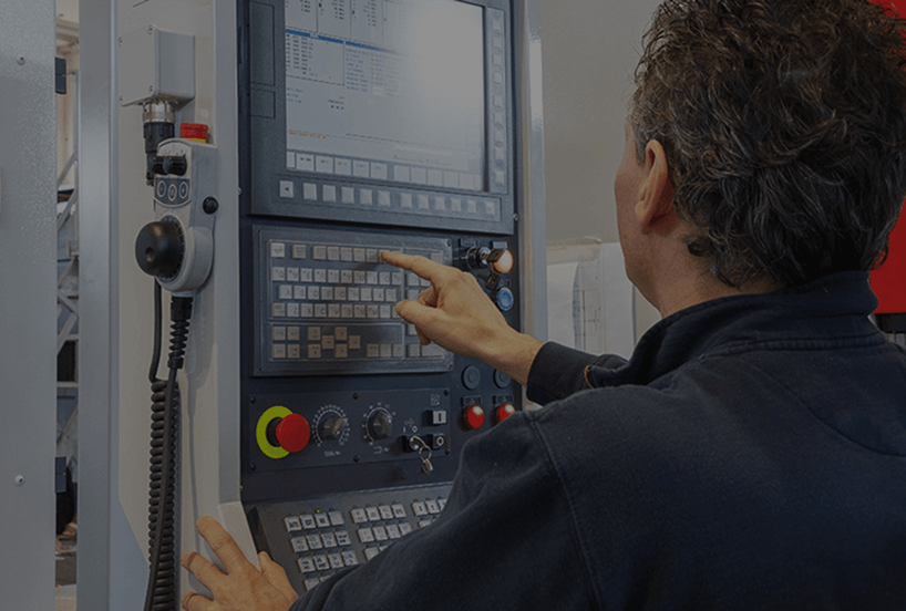
Witness the operational precision of our horizontal machining centers in action. See how an integrated U-axis facing head performs heavy facing, internal turning, and high-speed milling on large industrial castings.
With over 60 years of engineering legacy, more than 2,000 installations worldwide across 100+ countries, and complete lifecycle support, Nanjing Fortis provides turnkey machining solutions engineered to your exact component blueprints.