
Executive Summary: Information Gain for Engineering Procurement
Fluid ends represent the hydraulic heart of high-pressure reciprocating plunger pumps used in hydraulic fracturing, well servicing, acidizing, and heavy industrial slurry pumping. Operating under continuous cyclic pressure pulsation reaching 15,000 to 22,500+ PSI (103 to 155+ MPa), these massive forged steel blocks suffer severe fatigue failure if internal geometry, cross-bore radii blending, and thread pitch tolerances deviate by even sub-millimeter fractions. This whitepaper presents an advanced manufacturing strategy utilizing Stationary Part Horizontal U-Axis CNC Machining Centers to eliminate transfer alignment stack-up, reduce micro-cracking risks, and consolidate 5 separate VTL/HMC machining setups into a single high-precision operation.
1. The Fluid End Metallurgical & Mechanical Reality
A fluid end (or hydraulic block) converts rotary mechanical energy into high-pressure fluid flow through reciprocating plungers, suction valves, and discharge valves. Because of the aggressive media pumped—including abrasive proppants, slickwater, concentrated acids, and harsh chemicals—the structural integrity of the block is pushed to its physical limitations.
From a metallurgical perspective, fluid end blocks are fabricated from high-yield, high-tensile forged alloy steels and stainless steels. Common material grades include:
- AISI 4340 / 4140 Alloy Steel: Vacuum-degassed, quenched, and tempered to achieve high core toughness and yield strength exceeding 100,000 PSI.
- 15-5 PH & 17-4 PH Stainless Steel: Precipitation-hardened martensitic stainless steels providing superior resistance to cavitation erosion and mild corrosive fluids while maintaining extreme fracture toughness.
- Duplex & Super Duplex Stainless Steels (e.g., UNS S32750 / 2507): Specified for aggressive sour gas (H2S) environments and hyper-saline fluid applications due to exceptional pitting resistance equivalent numbers (PREN > 40).

Machining these dense forgings demands high static and dynamic machine rigidity. High-nickel alloys and precipitation-hardened steels generate severe thermal loads at the cutting zone and work-harden rapidly under vibration or chatter. Consequently, successful CNC machining for fluid ends requires a machining platform capable of delivering high spindle torque at lower RPMs, immense dampening capacity, and absolute positioning repeatability.
2. Technical Bottlenecks in Conventional Fluid End Machining
Traditional manufacturing lines produce fluid ends by routing multi-ton forged blocks through a series of discrete machine tools—typically starting with a gantry mill or heavy horizontal milling machine (HMC) for exterior squaring and rough face milling, transferring to a Vertical Turning Lathe (VTL) for large bore facing and turning, and finally moving to a 4-axis HMC for cross-drilling and valve cover threading.
This traditional multi-machine workflow creates severe operational bottlenecks and quality vulnerabilities:
A. Cumulative Fixture Alignment Stack-Up
Every time a 5,000 lb forged steel block is unclamped, flipped, and reclamped onto a new machine fixture, datum errors compound. Concentricity between the plunger bore and the valve seat bores often degrades beyond the critical limit (< 0.025 mm). Misalignment causes side-loading on plungers, leading to accelerated seal degradation, fluid bypass, and catastrophic washouts.
B. Cross-Bore Intersection Stress Concentration
The internal junction where the horizontal plunger bore meets the vertical suction and discharge bores creates a severe geometric stress raiser. Under cyclic pressure loading (up to 120 strokes per minute at 15,000 PSI), stress intensifies by a factor of 3x at un-blended sharp internal corners. Conventional boring bars on standard HMCs struggle to generate complex, perfectly smooth, blended internal radii at these internal intersections, leaving microscopic tool marks that act as nucleation sites for fatigue micro-cracking.
C. Severe Tool Deflection & Chatter in Deep Bore Contouring
Deep valve seat profiles and internal thread relief grooves require long-overhang tooling. Standard rotating spindles experience centrifugal deflection and chatter when extended deep inside a block. This results in poor surface finish (Ra > 1.6 µm), out-of-round valve seats, and uneven thread engagement on high-pressure valve cover retainers.
3. Critical Anatomical Features & Tolerance Matrix
To understand the rigorous demands of fluid end production, engineers at Nanjing Fortis Storage Equipment Manufacturing Co., Ltd. have cataloged the key anatomical features, required manufacturing tolerances, and failure consequences in Table 1 below:
| Anatomical Feature | Machining Process Requirements | Target Tolerance & Finish | Failure Consequence of Deviation |
|---|---|---|---|
| Plunger Bores (Triplex / Quintuplex) | Deep precision boring, fine contouring, and internal grooving for seal retainers. | Diameter: ±0.012 mm Surface Finish: Ra < 0.4 μm |
Rapid seal destruction, fluid leakage, wall erosion, plunger binding. |
| Suction & Discharge Valve Seats | Taper facing, internal seat angle turning, precision blending to fluid passage. | Taper Angle: ±0.05° Concentricity: < 0.015 mm |
Poor valve sealing, pressure cavitation, high-velocity fluid washout. |
| Cross-Bore Intersections | 3D internal radii profiling, smooth transition chamfering, polish-milling. | Blend Radius: ±0.10 mm No discrete step marks |
High stress concentration, micro-crack nucleation, block fatigue rupture. |
| Valve Cover & Suction Cover Threads | Heavy internal thread milling or single-point U-axis taper threading (ACME / Buttress). | Class 2B / 3B Fit Pitch Dia: ±0.025 mm |
Thread stripping under 15k PSI thrust load, catastrophic cover ejection. |
| Manifold & Gauge Ports | Face milling, drilling, rigid tapping (SAE / Code 61 / Code 62 flange faces). | Flatness: 0.010 mm over 100mm | External fluid weeping, flange gasket blow-outs. |
4. The Trevisan Breakthrough: Stationary Part U-Axis Technology
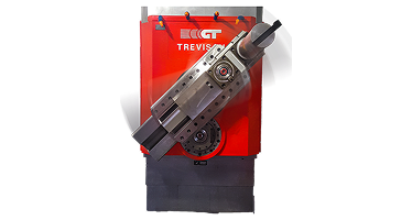
To overcome the fundamental limitations of multi-machine manufacturing, Nanjing Fortis Storage Equipment Manufacturing Co., Ltd. integrates original Trevisan machine technology featuring an Integrated Horizontal U-Axis Contour Facing Head combined with a Dual-Spindle Design.
How Stationary Part Machining Redefines Fluid End Production
On a traditional lathe or VTL, a multi-ton, asymmetric forged block must be rotated at high speeds to perform turning and facing operations. Rotating an unbalanced 6,000 lb block creates immense centrifugal forces, machine vibration, and safety hazards, severely restricting cutting speeds and depth of cut.
Trevisan horizontal U-axis machining centers invert this process completely:
- The Fluid End Block Remains 100% Stationary: The heavy forged block is clamped securely onto a rigid, heavy-duty CNC rotary index table (B-axis). It never rotates at turning speeds.
- The U-Axis Facing Head Rotates and Contours: The turning tool is mounted on a sliding tool carrier inside the rotating tool head. The radial position of the tool stroke (U-axis) is fully controlled by the CNC system dynamically while the spindle rotates.
- Single-Point Turning on a Milling Platform: Complex internal tapers, valve seat angles, internal threads, spherical radii, and face grooves are turned using single-point carbide inserts driven by the CNC U-axis, achieving standard lathe surface finishes (Ra 0.4–0.8 µm) on a horizontal machining center.
Dual-Spindle Architecture: Uncompromised Milling & Turning
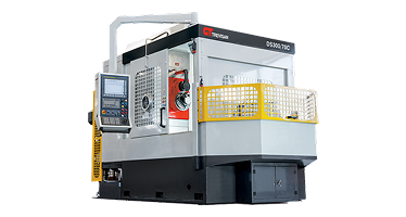
Unlike conventional machines that attempt to use weak facing head attachments on a standard milling spindle, Trevisan machines feature two independent concentric spindles within a single spindle head assembly:
- Spindle 1 (Heavy Quill Milling Spindle): An oversized, ultra-rigid quill spindle dedicated to heavy face milling, deep hole drilling, rigid tapping, and high-rate material removal.
- Spindle 2 (U-Axis Facing Head Spindle): A dedicated facing head equipped with a numerically controlled radial slide (U-axis) for internal boring, single-point taper turning, and precision profiling.
By switching automatically between the milling quill and the U-axis facing head within the same CNC program, the machine executes heavy roughing milling and fine internal turning without manual operator intervention or head-changing downtime.
5. Advanced Machining Strategies for Stress Mitigation
By leveraging stationary part U-axis machining, Nanjing Fortis Storage Equipment Manufacturing Co., Ltd. has developed specialized machining cycles specifically engineered to extend the fatigue life of fluid end blocks:
A. 3D Interpolated Cross-Bore Radii Blending
Using the synchronized motion of the U-axis along with X, Y, and Z axes, the cutting tool executes true 3D contouring at the cross-bore intersection. Instead of leaving a sharp 90-degree intersection or an un-blended chamfer, the machine generates a continuous parabolic radius blend. Finite Element Analysis (FEA) proves that generating a smooth parabolic blend at the bore junction reduces stress concentration factors from 3.1 down to 1.4, effectively doubling or tripling the operational fatigue life of the fluid end in the field.
B. Single-Point Internal Taper Threading
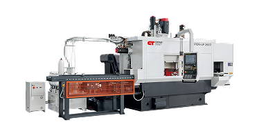
Large internal threads for valve covers (e.g., 6"-4 ACME or custom Buttress profiles) subjected to high pressure pulsation are prone to fatigue failure at the root of the first thread pitch. Thread milling with multi-tooth cutters can leave micro-fissures or chatter marks. Using the U-axis facing head, thread cutting is performed as a single-point turning operation. The tool tracks the exact thread flank angle while continuously varying radial depth to generate a smooth, polished thread root radius, maximizing load distribution across all engaged threads.
C. High-Pressure Through-Spindle Coolant (TSC) Strategy
Deep plunger bore machining in forged 15-5PH stainless steel generates tight, stringy chips that can score polished bore walls if re-cut. Trevisan machines integrate high-pressure through-spindle coolant systems delivering 70 to 100 bar (1,015 to 1,450 PSI) directly through the cutting tool vector. This forces instant chip breaking, flushes swarf rapidly out of deep blind holes, and maintains constant temperature to prevent thermal micro-cracking.
6. Quality Assurance & NDT Validation Protocols
To ensure zero-defect delivery in high-pressure oilfield pumps, manufacturing processes implemented by Nanjing Fortis Storage Equipment Manufacturing Co., Ltd. adhere to rigorous international Quality Assurance (QA) and Non-Destructive Testing (NDT) guidelines:
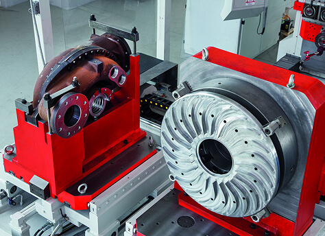
- In-Process Tactile Probing: Automated spindle-mounted touch probes inspect raw casting/forging allowances prior to roughing, align internal bore datums automatically, and verify critical seat dimensions before un-clamping.
- Surface Roughness Profilometry: Post-machining verification using contact profilometers ensures plunger bores and valve seat tapers achieve Ra < 0.4 µm without requiring manual hand-polishing.
- Ultrasonic Flaw Detection (UT): 100% volumetric inspection of raw forgings and semi-finished blocks to verify absence of internal inclusions, voids, or forging bursts.
- Magnetic Particle Inspection (MPI) / Dye Penetrant (PT): Performed specifically around cross-bore intersections and thread roots post-machining to confirm zero surface micro-fissures prior to pressure testing.
- Hydrostatic Proof Testing: Completed fluid end blocks undergo static water-pressure testing up to 1.5x working pressure (e.g., testing to 22,500 PSI for a 15,000 PSI rating) to validate zero structural weeping or yield strain.
7. Economic & TCO Analysis for B2B Procurement
For plant operations directors, manufacturing engineers, and procurement managers, upgrading to a specialized CNC machining platform for fluid ends represents a significant capital expenditure. Below is a comparative Total Cost of Ownership (TCO) evaluation comparing traditional multi-machine production lines against a single consolidated Trevisan Horizontal U-Axis Machine Cell.
| Economic Metric | Traditional Multi-Machine Line (1 VTL + 2 HMCs + 1 Radial Drill) |
Consolidated Trevisan Cell (1 Horizontal U-Axis Machine) |
Operational Impact & Savings |
|---|---|---|---|
| Number of Machine Units | 4 Dedicated Machines | 1 Integrated Machining Center | 75% reduction in footprint |
| Machining Setups Required | 5 Separate Fixture Setups | 1 or 2 Setups (Complete Part) | 60–80% reduction in setup labor |
| Floor-to-Floor Cycle Time | 14 to 18 Hours / Block | 5.5 to 7.5 Hours / Block | Over 55% cycle time reduction |
| Operators Required per Shift | 3 to 4 Skilled Machinist | 1 Cell Operator | 70% labor cost savings |
| Scrap Rate from Alignment Errors | 3.5% to 5.0% average | < 0.2% guaranteed | Saves $150k+ annually in lost forgings |
| Annual Floor Space Consumed | Approx. 3,200 sq. ft. | Approx. 850 sq. ft. | Frees up floor space for assembly |
B2B ROI Conclusion
While the initial capital cost of an integrated U-axis machining center is higher than a single standard HMC, the elimination of 3 additional machine tools, reduction of labor overhead, and dramatic scrap rate drop yield an average payback period of 14.2 months for high-volume fluid end manufacturers.
Specialized Machining Solutions for Fluid End Production
Nanjing Fortis Storage Equipment Manufacturing Co., Ltd. offers a comprehensive line of heavy-duty CNC machining centers tailored for oilfield hydraulics and heavy industrial valve/pump manufacturing:
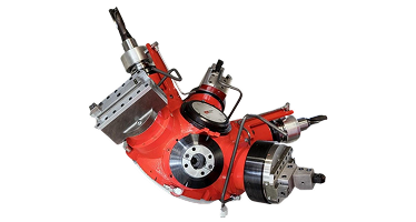
Modulo Equipe Series
High-flexibility modular cells designed for rapid changing between triplex and quintuplex fluid end blocks.
View Specifications →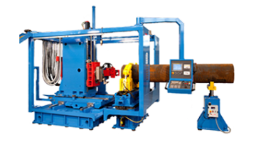
Specialized Machines
Custom engineering solutions designed specifically for large-bore mud pumps, frac blocks, and offshore riser components.
View Specifications →