
Discover how Trevisan's Horizontal Machining Centers minimize setup time and labor costs — Learn More →
Insights & Updates

CNC Machining Insights & Technical Blog

Explore expert guides, engineering innovations, and industry developments from Nanjing Fortis Storage Equipment Manufacturing Co., Ltd.

0%

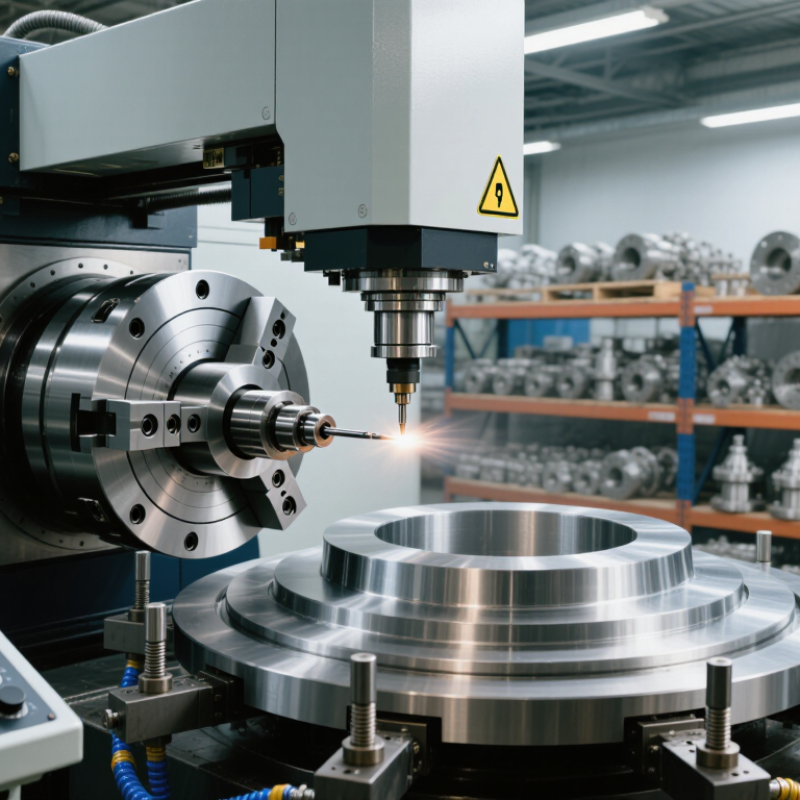
A U-axis facing head machine is a CNC machining system designed for large, accurate circular features. It uses a programmable U-axis to move the cutting tool radially while the spindle rotates. This movement allows the machine to face, bore, groove, or finish surfaces with changing diameters. It differs from a conventional fixed-tool setup. The tool can adjust its cutting radius during one machining cycle.

The term is not perfectly standardized. Some manufacturers describe the U-axis as a radial slide, while others integrate it into a special facing head. That distinction matters when comparing machines. A reliable evaluation should examine the tool travel, spindle speed range, positioning accuracy, control functions, and maximum workpiece diameter. Manufacturer documentation remains essential.

On a shop floor, this equipment can machine large flanges, valve bodies, bearing seats, and stepped circular surfaces. Operators often reduce setup changes by completing several diameters in one clamping. That can improve concentricity and shorten production time. Small details matter. Tool balance, cutting depth, coolant delivery, and workholding rigidity directly influence surface quality.

However, a U-axis facing head machine is not automatically the best choice for every job. It may require specialized programming and experienced setup personnel. Poor calibration can create taper, uneven shoulders, or dimensional errors. Engineers should review real drawings, material conditions, tolerance requirements, and service support before selecting a machine. This guide explains the working principle, typical applications, advantages, limitations, and practical selection criteria. It also questions common assumptions, because impressive specifications do not always guarantee stable machining results.
What Is a U Axis Facing Head Machine?

U-Axis Facing Head Definition and Its Role in CNC Machining

What Is a U Axis Facing Head Machine?

A U-axis facing head is a CNC attachment with programmable radial tool movement. Unlike a standard spindle, it changes the cutting diameter during rotation. This motion supports facing, internal boring, chamfering, and controlled contouring on large workpieces. The tool may sweep from the center toward the outer edge. That flexibility reduces repeated setups and improves access to broad flanges or deep bores.

Its value becomes clearer as manufacturers pursue higher productivity. Grand View Research estimated the global CNC machine market at USD 88.9 billion in 2023. The same report forecasts an 8.3% compound annual growth rate from 2024 to 2030.

A U-axis facing head can support this growth by combining several operations within one machine cycle. Deloitte’s 2023 Smart Manufacturing Survey found that 86% of manufacturing leaders expect smart manufacturing to strengthen competitiveness within five years.

U-axis control fits that direction when its position, feed, and load data are monitored carefully.

In practice, accuracy depends on calibration, thermal stability, spindle alignment, and tool overhang. A 0.02 mm radial error can create a 0.04 mm diameter error. That detail is easy to miss. Operators should verify the offset at working temperature and inspect the first machined face.

Machine builders may define U-axis motion differently, so the control manual remains essential. I have found that programming flexibility does not replace sound cutting data. It can even hide poor setup decisions.

U-Axis Radial Motion and Its Effect on Facing Diameter and Cutting Paths

What Is a U Axis Facing Head Machine?

A U-axis facing head machine uses radial tool movement during face machining. Unlike a fixed tool, the cutter can travel inward or outward from the spindle centerline. This movement changes the cutting diameter while the spindle rotates. A small radial shift can create a large change across the workpiece face.

U-axis motion also reshapes the cutting path. The tool may follow a straight radial route, a stepped path, or a controlled interpolated curve. A programmed outward movement can machine a broad diameter efficiently. An inward movement can finish near the center without forcing the tool into an unstable position. Cutting speed must be checked across the path. The outer diameter usually produces a higher surface speed than the center.

In practical setup work, I verify the U-axis zero with a test cut and a diameter measurement. This catches offset errors early. It also reveals whether the tool nose radius matches the programmed path. A wrong compensation value may leave a visible ring on the face. It can also alter the final diameter. Keep tool clearance in mind. The head, holder, and workpiece may occupy different radial zones. My first setups sometimes relied too heavily on simulation. Real vibration and insert wear were less predictable. That is worth checking. Steady feed control, conservative depth of cut, and repeated measurement usually produce more reliable facing results.

Core Components: Servo Drive, Radial Slide, Tool Holder, and CNC Control

What Is a U Axis Facing Head Machine?

Core Components: Servo Drive, Radial Slide, Tool Holder, and CNC Control

A U axis facing head machine adds controlled radial movement to a rotating spindle. This movement lets the cutter face large diameters, machine grooves, and create accurate profiles without moving the entire machine table. The servo drive supplies this motion with measured speed and position. Its response affects surface finish, dimensional accuracy, and cutting stability.

The radial slide carries the tool across the workpiece. It must resist vibration while moving smoothly through the programmed path. Even small slide backlash can leave visible steps on a wide face. The tool holder connects the cutter to the slide, so rigidity and correct balance matter. A short, secure setup usually performs better than an extended one.

The CNC control coordinates spindle rotation, radial travel, feed rate, and cutting depth. Skilled operators check the tool offset, slide centerline, and actual runout before production. A simulation helps, but it cannot reveal every setup problem. In practice, the first pass is rarely perfect. Chips may pack near the holder, or the cutting edge may wear sooner than expected. Measuring the face after a light test cut often exposes errors before they become expensive. Calibration records and repeatable inspection methods also improve reliability across different workpieces.

ISO 230-2 Accuracy Metrics for U-Axis Positioning and Repeatability

What Is a U Axis Facing Head Machine?

A U-axis facing head machine uses a radial slide to vary the cutting diameter during machining. Unlike a conventional linear axis, the U axis often works inside a rotating spindle assembly. Its motion directly affects facing accuracy, grooves, tapers, and internal profiles. Even a small radial error can change the finished diameter.

ISO 230-2 provides a practical framework for checking U-axis positioning accuracy and repeatability. A technician defines several target positions across the working stroke, then measures each position from consistent approach directions. A calibrated laser interferometer or high-accuracy linear measuring system may be used. The test should record machine temperature, measurement direction, feed rate, and stabilization time. These details matter.

Positioning accuracy shows how closely the U axis reaches commanded locations. Repeatability shows how consistently it returns to those locations. Bidirectional tests can reveal reversal effects, friction, backlash, or servo behavior. A one-direction test may look excellent. It can still hide a problem. I have seen reports with impressive averages but weak results near the stroke ends. That is why engineers should review individual deviations, not only the final chart. Control resolution is not the same as mechanical accuracy. A displayed increment may be tiny, while the actual radial position remains unstable. ISO 230-2 results also depend on the selected evaluation method and test conditions. Small assumptions can change the interpretation.

U-Axis Facing Head Accuracy: ISO 230-2 Positioning Metrics

Representative linear U-axis test data showing mean bidirectional positioning error and positioning repeatability at six target positions. Values are expressed in micrometres (μm); lower values indicate better performance.

ISO 230-2 evaluates machine-tool axis positioning performance through repeated measurements at defined target positions. This representative dataset is intended for technical illustration and does not represent a specific machine or manufacturer.

Applications, Machine Compatibility, and Selection Criteria for U-Axis Heads

What Is a U Axis Facing Head Machine?

Applications, Machine Compatibility, and Selection Criteria for U-Axis Heads

A U-axis facing head adds programmable radial movement to a machine’s spindle. It shifts a cutting tool away from the centerline while the spindle rotates. This supports off-center turning, internal grooving, boring, and face contours on large flanges, rings, and housings. Think of it as a compact polar-coordinate system. That description is useful, but not complete. Stiffness, balance, and control response determine whether the cut is genuinely productive.

Application evidence matters. The International Federation of Robotics reported 4.28 million industrial robots operating worldwide in 2023, a 10% annual increase. This reflects demand for integrated, repeatable production, although robots do not prove every U-axis project is justified. Grand View Research forecasts continued CNC machine market expansion through 2030. Those figures suggest investment momentum, not automatic payback. Measure cycle-time reduction, tool life, setup savings, and surface finish on your own parts.

Compatibility begins with the host machine. Check spindle taper, drawbar capacity, speed range, torque, coolant delivery, encoder feedback, and available clearance. Confirm that the CNC can command radial position and synchronize it with spindle rotation. Post-processor support is often overlooked. Select the head by radial stroke, cutting force, accuracy, balancing grade, and service access. For heavy facing, prioritize rigidity. For complex contours, prioritize interpolation accuracy and software stability. An honest review should include thermal growth, clamping errors, and operator training. Impressive demonstrations can fail during production. The missing detail is usually integration, not cutting power.

What Is a U Axis Facing Head Machine? - Applications, Machine Compatibility, and Selection Criteria for U-Axis Heads

Category Key Dimension Technical Information Selection or Application Guidance
Definition U-axis facing head A U-axis facing head is a programmable radial slide or offsetting tool head mounted on a machine spindle. The slide moves the cutting tool toward or away from the spindle centerline while the spindle rotates. Select a U-axis head when a turning or milling operation requires a variable cutting diameter, an eccentric profile, or controlled radial movement that a fixed tool cannot produce.
Operating Principle Radial tool movement The U-axis normally controls the radial position of the tool relative to the spindle axis. Depending on the head design, the movement may be driven by machine-axis commands, a programmable internal mechanism, or a combination of both. Confirm how the head receives motion commands and whether the machine control can support the required interpolation, offsets, and feed-rate settings.
Typical Machines Machine compatibility Common host machines include CNC turning centers, vertical or horizontal machining centers, mill-turn machines, and selected large CNC lathes with suitable spindle interfaces. Match the head to the machine’s spindle taper, tool-clamping method, allowable tool length, spindle speed range, coolant system, and available control functions.
Machine Interface Spindle and tool connection Important interface details include taper type, flange dimensions, retention method, maximum permissible mass, toolholder arrangement, orientation features, and automatic tool-change requirements. Use the machine’s actual spindle and toolholder drawings rather than relying only on nominal taper size. Check clearance during tool changes and verify that the head can be securely oriented.
Primary Applications Large-diameter facing A U-axis head can face large circular areas when the required diameter exceeds the practical range of a conventional fixed turning tool or when the tool must travel radially under numerical control. Compare the required face diameter, radial stroke, cutting depth, spindle torque, and available clearance with the head’s rated operating envelope.
Primary Applications Internal and external grooves Programmable radial movement can support internal grooves, external grooves, reliefs, recesses, and stepped profiles when the tool geometry and head stroke are suitable. Verify minimum and maximum working diameters, groove width, tool access, insert geometry, and whether the required profile can be interpolated without overloading the slide.
Primary Applications Tapered and contoured surfaces Coordinated radial movement and spindle rotation can create certain tapered, contoured, or non-standard rotational surfaces. The achievable shape depends on control resolution, stroke, and cutting-tool geometry. Confirm that the CNC control supports the necessary coordinated motion and that the post-processor can generate the correct U-axis commands for the selected head.
Primary Applications Eccentric machining A programmable offset can be used for selected eccentric features, provided the head and machine control can maintain the required radial position and cutting stability throughout the cycle. Evaluate eccentricity, workpiece balance, spindle speed, dynamic loads, fixture rigidity, and the effect of interrupted cutting before approving the process.
Performance Radial stroke Radial stroke defines the usable range of tool movement. The resulting diameter range is influenced by the head’s center position, tool projection, insert geometry, and workpiece clearance. Calculate the required tool-center movement and leave additional clearance for approach, retract, tool wear, workholding, and safe machine motion.
Performance Positioning resolution Positioning resolution affects the smallest programmable radial increment and therefore influences dimensional control, surface transitions, and the accuracy of contoured features. Choose a resolution appropriate to the part tolerance and surface requirement. Resolution alone does not guarantee accuracy; backlash, thermal effects, rigidity, and calibration are also important.
Performance Cutting load and rigidity The head must withstand cutting forces, vibration, thermal loads, and repeated acceleration without excessive deflection. Longer tool projection generally increases bending and reduces process stability. Prioritize a rigid head and short tool setup for heavy cuts. Use conservative cutting parameters during initial trials and verify vibration, spindle load, and dimensional drift.
Control Requirements U-axis command support The machine control must support the motion method used by the head, including axis addressing, feed commands, coordinate offsets, interpolation, limits, and emergency retraction behavior. Obtain the head’s programming manual and test the required commands in a controlled environment. Confirm alarm handling, travel limits, and compatibility with the machine’s CNC software version.
Control Requirements Post-processor integration CAM output may require special post-processor logic for U-axis motion, tool orientation, coordinate transformation, cutter compensation, feed calculation, and safe start or end positions. Select a solution with a verified post-processor or plan for custom programming. Simulate the complete toolpath to detect overtravel, collisions, incorrect offsets, and unexpected radial movement.
Coolant and Tooling Coolant delivery Coolant may be delivered externally or through the spindle and tool head, depending on the design. Flow rate, pressure, sealing, chip evacuation, and hose routing can affect reliable operation. Match coolant capability to the material, cutting speed, insert type, and chip-control needs. Check that hoses and passages do not interfere with radial motion or automatic tool changing.
Coolant and Tooling Cutting tools and inserts Tool selection depends on workpiece material, cutting direction, groove or facing geometry, required surface finish, cutting depth, and the available tool pocket or holder system. Use tools recommended for the material and application, while keeping tool overhang as short as possible. Confirm insert clearance at the smallest and largest programmed diameters.
Workpiece Range Part size and envelope The usable part range is limited by maximum workpiece diameter, spindle opening, chuck or fixture dimensions, head body diameter, radial stroke, tool reach, and machine-axis travel. Create a complete 3D clearance check that includes the workpiece, fixture, head body, toolholder, coolant lines, tailstock or opposing spindle, and machine enclosure.
Accuracy Repeatability and calibration Finished-part accuracy depends on head repeatability, machine positioning accuracy, spindle runout, tool setup, thermal stability, calibration, and cutting-force deflection. Define acceptance criteria for radial positioning, repeatability, surface finish, and dimensional accuracy. Include a setup verification routine and periodic inspection of the head and tool interface.
Safety Rotational balance and limits An offset or asymmetrical head can produce additional centrifugal forces and vibration at higher spindle speeds. Exceeding rated speed, mass, or stroke limits can damage the head or machine. Follow the head manufacturer’s rated speed, mass, balance, stroke, and cutting-load limits. Use guarding, prove-out procedures, single-block operation, and reduced speed during first-run verification.
Maintenance Inspection and service Routine care may include cleaning the taper and tool interface, checking fasteners, inspecting seals and coolant passages, verifying radial movement, and monitoring backlash or abnormal noise. Establish maintenance intervals based on duty cycle, cutting load, coolant exposure, and operating environment. Remove the head from service if movement becomes rough or dimensional repeatability deteriorates.
Selection Criteria Application fit The most important factors are required feature type, diameter range, radial stroke, workpiece material, cutting load, accuracy, surface finish, production volume, and expected setup frequency. Select the smallest head that safely covers the required envelope while providing adequate rigidity, tooling flexibility, coolant access, control compatibility, and serviceability.
Selection Criteria Cost and productivity Total cost includes the head, toolholders, cutting tools, control integration, programming, setup time, maintenance, inspection, and possible machine modifications. Compare the complete process cost and cycle-time improvement rather than the purchase price alone. A suitable U-axis head can reduce special fixtures or secondary operations when properly integrated.

FAQS

What does a U-axis facing head do?

It moves the cutting tool radially while the spindle rotates. This changes the machined diameter and cutting path. Small movement matters.

Which operations can use U-axis radial motion?

It supports face machining, off-center turning, internal grooving, boring, and curved face contours. Typical parts include flanges, rings, and housings. Large faces benefit most.

How does U-axis movement change a cutting path?

The tool can travel straight outward, step across the face, or follow an interpolated curve. Outward motion machines broad diameters efficiently. Inward motion can finish near the center more safely.

Why must cutting speed be checked across the face?

The outer diameter usually has higher surface speed than the center. Feed and speed settings may need adjustment across the radial path. A single setting may not suit every zone.

How can I verify the U-axis zero?

Make a controlled test cut and measure the resulting diameter. This can reveal offset errors before production. Check it twice.

What happens when tool-nose compensation is incorrect?

The programmed path may not match the insert’s actual cutting point. A visible ring can remain on the face. The final diameter may also shift.

What machine details should be checked before installing a U-axis head?

Check the spindle taper, drawbar capacity, speed range, torque, coolant delivery, and clearance. Confirm encoder feedback and radial-position control. Post-processor support also matters.

How should a U-axis head be selected for production?

Compare radial stroke, cutting force, accuracy, balance, rigidity, and service access. Heavy facing needs stiffness. Complex contours need accurate interpolation and stable software.

Can simulation alone guarantee successful machining?

No. Real vibration, thermal growth, clamping errors, and insert wear may differ from simulation. I once trusted simulation too much. Measure repeatedly during setup.

Conclusion

A U-axis facing head machine is a CNC machining attachment or integrated unit that enables controlled radial movement while a cutting tool rotates around the spindle axis. Unlike a conventional facing operation with a fixed tool position, the U-axis allows the tool to move inward or outward across the workpiece surface. This adjustable motion determines the facing diameter, cutting path, and material removal pattern, making it useful for large bores, stepped faces, shoulders, and precision circular features.

Its main components include a servo drive for accurate radial positioning, a radial slide that guides the tool movement, a tool holder for secure cutting-tool installation, and CNC control software that coordinates spindle rotation and U-axis travel. Performance is commonly evaluated through ISO 230-2 accuracy and repeatability measurements. When selecting a U-axis facing head machine, users should consider required diameter range, load capacity, control compatibility, spindle interface, machine rigidity, and achievable precision. These factors help ensure reliable operation across suitable CNC lathes, machining centers, and specialized boring equipment.

Ethan

Ethan

Ethan is a dedicated marketing professional with a profound understanding of our company’s core products and services. With years of experience in the industry, he has honed his skills in creating compelling content that resonates with our audience. As a key contributor to our professional blog,......