Choosing CNC machining for pumps is not just a question of making a part fit. Impellers, housings, shafts, and wear rings must handle pressure, fluid exposure, vibration, and continuous rotation. A small mismatch at the seal face can cause leakage or shorten service life. Details matter.
The U.S. Department of Energy’s Improving Pumping System Performance: A Sourcebook for Industry notes that pumping systems can account for 25–50% of energy use in some industrial facilities. That range is not a promise of savings, but it shows why pump efficiency deserves careful attention. The Hydraulic Institute and Europump’s Pump Life Cycle Costs guide also emphasizes evaluating costs across a pump’s service life, rather than focusing only on purchase price. Machining choices can affect both performance and maintenance.
So, how should manufacturers choose CNC machining for pumps? Start with the fluid, operating pressure, target flow, material, annual volume, and required tolerances. Then assess the part’s geometry and critical features, such as concentric bores, impeller balance, and sealing surfaces. CNC milling and turning can produce accurate metal components, but they are not automatically the best route for every design. Tool access, setup time, finishing, inspection, and material waste all matter. This is where assumptions can fail. A highly precise feature may add cost without improving pump performance. A seemingly minor surface requirement may be essential for sealing. The right process depends on evidence from drawings, service conditions, and prototype testing—not a machining label alone.
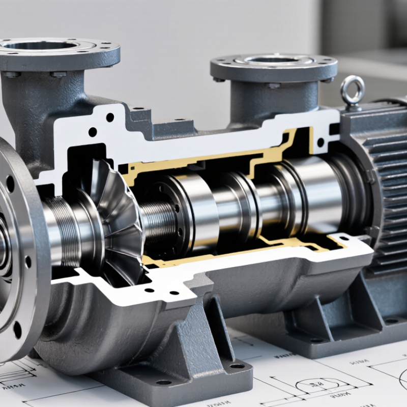
Map Flow, Head, and Pressure Requirements to API 610 Pump Service
Map the pump’s actual duty point before choosing CNC-machined parts.
Record flow, total head, suction conditions, fluid temperature, and pressure at normal and peak operation. A pump handling 120 cubic metres per hour at 45 metres of head may need different impeller geometry and casing details from one facing frequent pressure surges. Small errors matter.
API 610 covers centrifugal pumps for petroleum, petrochemical, and natural gas services. Its requirements make material selection, shaft stiffness, clearances, and inspection relevant to machining decisions. CNC machining can hold repeatable impeller and seal-chamber dimensions, but tighter tolerances are not automatically better; they must fit the design and operating conditions.
The U.S. Department of Energy’s Improving Pumping System Performance sourcebook reports that pumping systems use nearly 20% of global electricity. That is a strong reason to check efficiency across the operating range, not just at one test point.
For an API 610 service, share the duty envelope and required inspection records with the machining team before production. Specify measurable features, such as impeller eye diameter, bore concentricity, and seal-face runout, rather than asking for “high precision.” Verify these against the pump drawing and applicable standard edition. One detail can be missed. A real-world duty point may drift as filters foul or valves change position, so leave room for review instead of treating the initial figures as perfect.
Choose Wetted Materials Such as ASTM A743 CF8M Stainless Steel
When selecting CNC-machined pump components, identify every surface the liquid touches. That includes the casing, impeller, shaft sleeve, and fasteners. ASTM A743 CF8M is a cast stainless steel grade with molybdenum, often considered for water and mildly corrosive fluids. It can offer useful corrosion resistance, but the grade name alone cannot confirm compatibility.
Check the fluid’s chemistry, temperature, concentration, and flow conditions before choosing the material. Chlorides may cause pitting or crevice corrosion, especially beneath deposits or around narrow gaps. A component that performs well in clean water may behave differently in warm brine. Small details matter. Ask for material certificates and confirm the casting’s condition before machining. Then review the finished part for porosity, surface damage, and dimensions at sealing faces.
CNC machining can create accurate fits and smooth sealing surfaces, but it cannot correct a poor material choice. Specify the required finish and tolerances for each wetted feature, rather than applying one requirement to the entire part. If the service conditions are uncertain, consult a corrosion specialist and test representative material in the actual fluid. CF8M is a sensible candidate in some duties, not a universal answer. That distinction is easy to overlook.
Set Shaft-and-Bore Fits Using ISO 286 H7/g6 Tolerance Classes
How to Choose CNC Machining for Pumps?
For a pump shaft running in a machined housing, ISO 286 H7/g6 is a common clearance-fit starting point. The ISO 286-2 tolerance tables give an 18–30 mm H7 bore a 0 to +21 μm tolerance. The matching g6 shaft is −7 to −20 μm. That yields 7–41 μm diametral clearance before accounting for surface finish, temperature, or measurement uncertainty. Small numbers matter. A burr at the bore entrance can spoil an otherwise accurate fit.
The U.S. Department of Energy’s Improving Pumping System Performance sourcebook reports that pump systems use nearly 20% of global electrical energy. That is a broad industry figure, not a promise that tighter tolerances will save energy. On the shop floor, check bore size with a calibrated gauge and measure the shaft at several positions. CNC turning and boring can hold the specified dimensions, but tool wear and setup shifts still need control. I would not treat the table as the whole design. Confirm shaft material, operating temperature, lubrication, and expected radial load before releasing the drawing. For sizes outside the 18–30 mm range, recalculate from the applicable ISO 286 size step rather than scaling these values.
How to Choose CNC Machining for Pumps? - Set Shaft-and-Bore Fits Using ISO 286 H7/g6 Tolerance Classes
| Nominal diameter range (mm) |
Example pump application |
H7 bore deviations (µm)
Lower / upper |
g6 shaft deviations (µm)
Lower / upper |
Minimum diametral clearance (µm) |
Maximum diametral clearance (µm) |
Fit selection note |
| 6 to 10 |
Small pump drive or support shaft |
0 / +15 |
−14 / −5 |
5 |
29 |
Provides clearance for a small, accurately machined locating or sliding fit. |
| 10 to 18 |
Compact pump shaft or bearing seat |
0 / +18 |
−17 / −6 |
6 |
35 |
Allows assembly and relative movement where the design calls for a clearance fit. |
| 18 to 30 |
Pump impeller or coupling shaft interface |
0 / +21 |
−20 / −7 |
7 |
41 |
Check that the available clearance suits the required alignment and operating motion. |
| 30 to 50 |
General-purpose pump shaft and housing bore |
0 / +25 |
−25 / −9 |
9 |
50 |
A useful starting point for a designed clearance fit; verify against load and lubrication needs. |
| 50 to 80 |
Medium pump shaft or sleeve interface |
0 / +30 |
−29 / −10 |
10 |
59 |
Consider bearing type, shaft support, temperature, and operating clearance. |
| 80 to 120 |
Larger pump shaft or bearing housing fit |
0 / +35 |
−34 / −12 |
12 |
69 |
Confirm that the resulting clearance is acceptable at the pump’s operating temperature. |
| 120 to 180 |
Large pump shaft and bore interface |
0 / +40 |
−39 / −14 |
14 |
79 |
Use only when this clearance range matches the specific support and motion requirements. |
Values are ISO 286 limit deviations in micrometres for the listed nominal diameter steps. H7 bore deviations are 0 to the stated positive value; g6 shaft deviations are shown as lower to upper deviation. Minimum and maximum diametral clearances are calculated from the limiting bore and shaft sizes. Confirm the required fit for the actual pump design, materials, operating temperature, lubrication, and manufacturing process.
Specify Impeller Balance by ISO 21940-11 Grade, Such as G6.3
How to Choose CNC Machining for Pumps?
CNC machining can produce accurate impeller passages, hub bores, and mounting faces. But dimensional accuracy alone does not guarantee smooth operation. Specify the impeller’s balance quality using ISO 21940-11, such as grade G6.3, when that grade suits the pump’s operating speed and service conditions. The grade relates permissible residual unbalance to rotor speed; it is not a fixed weight limit for every impeller.
Give the machinist or balancing specialist the impeller mass, operating speed, and required mounting condition. State whether the requirement applies to the bare impeller or the assembled rotor. These details matter: a part balanced on one arbor may behave differently when installed on its shaft. Ask for a balance report that records the achieved result and test setup. G6.3 may be suitable for some duties, but it should not be copied blindly from another pump specification. A tighter grade can add cost without solving vibration caused by alignment, bearings, or flow conditions.
Tips: Confirm the balance grade with the pump designer. Keep the bore and mounting faces clean before testing. If the impeller will be trimmed later, rebalance it afterward. Small detail, big difference.
Permissible Specific Residual Unbalance for an Impeller at ISO Grade G 6.3
Illustrative limits calculated using the ISO balance-grade relationship G = e × ω. The values show permissible specific residual unbalance at different operating speeds.
For G 6.3, the permissible specific residual unbalance decreases as rotational speed increases. These values are not total unbalance; total permissible residual unbalance depends on rotor mass and is calculated as specific residual unbalance multiplied by rotor mass. Confirm the applicable requirements for the rotor and operating conditions.
Compare CNC Tolerances: ±0.13 mm Standard vs. ±0.025 mm Precision
For pump components, the difference between ±0.13 mm and ±0.025 mm can decide whether a shaft turns freely or a seal leaks. The first allows 0.26 mm of total variation; the second allows 0.05 mm. That is over five times tighter. These figures are useful comparison points, not universal machining classes: ISO 286-1:2010 assigns tolerance grades according to nominal size, so the same grade does not mean the same tolerance on every feature.
Choose the tighter range only where function demands it, such as a bearing seat, impeller hub, or close-running clearance. On a broad cover face, ±0.13 mm may be adequate and less costly to inspect. ASME Y14.5-2018 explains how geometric dimensioning and tolerancing communicates feature relationships; a size tolerance alone cannot control runout or concentricity. Check the drawing, material, and measurement method together. A micrometer, temperature, and setup variation can matter when the allowance is just 25 microns per side. Small numbers. Real consequences. In practice, I’d verify critical fits with a prototype, because calculations can miss how the assembled pump behaves.
Conclusion
Choosing CNC machining for pumps starts with defining the operating duty: required flow, head, pressure, fluid characteristics, and service conditions. These factors help determine the pump configuration and identify the critical components and surfaces that must be machined accurately. For pump service aligned with API 610 requirements, select wetted materials to suit the fluid and environment; ASTM A743 CF8M stainless steel may be appropriate where corrosion resistance is needed.
Next, specify fits and balance according to function. ISO 286 H7/g6 classes can guide shaft-and-bore fit selection, while impeller balance can be stated using ISO 21940-11, for example, grade G6.3. Set machining tolerances to match performance needs: ±0.13 mm may suit standard features, whereas precision features may require ±0.025 mm. Applying tighter tolerances selectively can support reliable assembly and operation without adding unnecessary machining cost.