
CNC machining for flanges demands more than a clean-looking face. A flange must match its drawing, seal reliably, and fit the mating assembly. A few microns of runout or a rough bolt-hole edge can complicate installation. That is why choosing a supplier means checking process control, inspection methods, and material experience—not just comparing prices.
Grand View Research estimated the global CNC machine market at USD 101.22 billion in 2023, with continued growth projected through 2030. This broad market figure is not flange-specific, but it signals expanding investment in precision manufacturing. For buyers, the practical questions remain local and measurable: Can the shop hold the required face finish? Does it inspect bolt-circle locations and concentricity? Can it provide material traceability and inspection records? W. Edwards Deming, a leading quality expert, wrote, “Quality comes not from inspection, but from improvement of the production process.” His principle applies here: a final check matters, but repeatable setup and machining matter more.
This guide explains how to compare flange machining capabilities, materials, tolerances, and quality documentation in 2026. It also looks at what a capable supplier should show before production begins, from a clear drawing review to a realistic inspection plan. There is no universal “best” shop. And a polished website proves little. The right choice depends on the flange’s service conditions, specification, batch size, and the supplier’s demonstrated ability to make each part consistently.
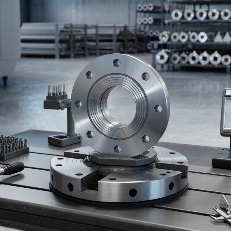
2026 Best CNC Machining for Flanges: How to Choose
ASME B16.5 covers pipe flanges and flanged fittings from NPS ½ through NPS 24, across Classes 150, 300, 400, 600, 900, 1500, and 2500. These are standard scope limits, not a promise that every size and class combination is available. The standard also specifies dimensions, tolerances, marking, materials, and pressure-temperature ratings. NPS is a nominal designation, not a direct measurement of flange diameter. Check the applicable ASME B16.5 tables before programming a CNC setup.
Class numbers do not equal allowable pressure in psi. Ratings depend on material group and operating temperature, as ASME B16.5’s pressure-temperature tables show. A machinist should verify the specified class, facing, bolt-hole pattern, and material against the drawing and purchase requirements. Small errors matter: a bolt circle shifted by a few millimeters can prevent field assembly. For example, a shop can use CNC boring and drilling to hold repeatable geometry, then inspect critical dimensions with calibrated gauges. Don’t guess. One detail is easy to overlook: finish requirements and gasket seating surfaces may affect tool choice and final inspection. A clean-looking flange is not necessarily a compliant one.
| ASME Class | NPS Size Scope | What the Class Indicates | CNC Machining and Inspection Considerations |
|---|---|---|---|
| 150 | NPS ½–24 | A pressure class designation under ASME B16.5. It is not a fixed pressure value in psi. | Confirm the specified flange type, facing, material, bolt-hole pattern, and dimensions against the applicable standard tables and project drawings. |
| 300 | NPS ½–24 | Pressure-temperature ratings depend on the flange material group and service temperature. | Check facing and gasket-contact surfaces, flange thickness, bolt-circle dimensions, and hole size against the required class and NPS. |
| 400 | NPS ½–24 | A separate standardized class; do not treat the class number as a direct pressure rating. | Use the specified material and class when selecting machining stock and tooling. Verify critical dimensions after machining. |
| 600 | NPS ½–24 | Allowable pressure varies with material and temperature; consult the applicable ASME B16.5 pressure-temperature rating tables. | Inspect the flange face, bore, bolt-hole location, and overall dimensions. Avoid assuming dimensions are interchangeable with another class. |
| 900 | NPS ½–24 | Use the rating tables for the selected material group and operating temperature to determine the applicable pressure-temperature rating. | Plan workholding to protect the flange face and maintain concentricity between the bore and facing where required by the drawing. |
| 1500 | NPS ½–24 | Class designation and rating must be assessed together with material and temperature. | Verify the exact NPS, class, facing, material specification, and dimensional requirements before programming or machining. |
| 2500 | NPS ½–12 | ASME B16.5 size coverage for Class 2500 extends through NPS 12. Pressure-temperature capability remains material- and temperature-dependent. | Confirm the applicable standard dimensions and drawing requirements carefully; use suitable inspection equipment for the specified tolerances. |
| Standard scope | NPS ½–24 for Classes 150–1500; NPS ½–12 for Class 2500 | ASME B16.5 covers pressure-temperature ratings, materials, dimensions, tolerances, marking, and testing for pipe flanges and flanged fittings within its scope. | NPS is a nominal size designation, not a direct measurement of flange outside diameter. Obtain flange dimensions from the applicable standard tables and confirm the governing edition. |
| Selection note: Choose a flange by the required NPS, class, material, facing, operating conditions, and applicable piping specification. The class number alone does not establish a universal allowable pressure. CNC machining guidance is general; standard dimensions, ratings, materials, and acceptance requirements should be verified against the applicable ASME B16.5 edition and project documents. | |||
It covers nominal pipe sizes from ½ to 24 inches and Classes 150 through 2500. Not every size and class combination is available.
No. Allowable pressure depends on material group and operating temperature. Check the applicable pressure-temperature tables.
Verify the class, facing, material, bore, thickness, bolt circle, and hole size against the drawing. Don’t guess.
Carbon steel may suit less corrosive service. F316L can offer better corrosion resistance in many wet or chloride-bearing environments, but conditions matter.
Request the material test report, heat number, and inspection results. Check heat treatment and the applicable specification edition, too.
The article gives 3.2–6.3 μm Ra as a common target. Confirm the project requirements and gasket type; Ra alone is not enough.
Measure the raised-face height and flange thickness at several points. Check bolt-hole locations and face runout against stated datums and tolerances.
No. Inspect critical dimensions, surface condition, and alignment. A smooth face can still be out of alignment, and I might overlook that at a glance.
Choosing CNC machining for flanges begins with defining the application and selecting the correct flange type, nominal pipe size, and pressure class. ASME B16.5 covers NPS ½–24 and Classes 150–2500, providing a useful framework for matching flange dimensions and ratings to service requirements. Material selection should follow the relevant ASTM specifications: for example, A105 is commonly specified for carbon-steel forgings, while A182 F316L applies to a corrosion-resistant stainless-steel option. Confirm that the material suits the operating environment before machining.
Next, match machine capacity, workholding, and setup strategy to the flange’s diameter, thickness, and geometry. Clearly specify critical dimensions, tolerances, and the required face finish; a typical target is 3.2–6.3 μm Ra when appropriate for the design. Complete the selection process by requiring dimensional inspection and documented quality controls aligned with ISO 9001, helping ensure the finished flange meets its drawings and applicable requirements.